Hallo und willkommen zu unserem heutigen Beitrag.
Unser günstiges 1,8 Zoll SPI TFT Display ermöglicht es, Informationen farblich mit einer Auflösung von 128 x 160 Pixeln darzustellen.
Dank der SPI-Schnittstelle, dem ST7735 Controllerchip, und der Vielzahl an Arduino-IDE-Bibliotheken ist die Implementierung in eigene Projekte sehr einfach.
Auch die Mikrocontroller mit ESP-32 können das TFT-Display über SPI ansteuern. Hierfür benötigt man jedoch für den ESP32 eine manuell angepasste Bibliothek. Ansonsten ist die Installation recht einfach.
Wie Sie den ESP32 über den Arduino-IDE Boardverwalter installieren, haben wir Ihnen bereits im Artikel "ESP32 über den Boardverwalter installieren" gezeigt. Wir gehen also davon aus, dass die aktuellen Boarddefinitionen für den ESP32 bereits installiert sind.
Installation der Bibliothek
Um das Display ansteuern zu können, verwenden wir die Bibliothek "TFT_eSPI" von Bodmer. Diese Bibliothek ist kein Bestandteil der Arduino Grundinstallation, kann jedoch in weniges Schritten über den Bibliotheksverwalter in der Arduino IDE Installiert werden.
Über das Menü "Sketch" -> "Bibliothek einbinden" -> "Bibliotheken verwalten ..." öffnen wir den Bibliotheksverwalter. Alternativ können Sie die Tastenkombination "Strg"+ "Shift" + "i" verwenden.

Im Suchfeld des Bibliotheksverwalters geben wir "TFT_eSPI" ein, und installieren "TFT_eSPI by Bodmer" in der aktuellen Version.

Notwendige Anpassungen
Damit die Bibliothek mit unserem ESP32 funktioniert, müssen wir die folgende Datei einmalig manuell anpassen.
Dazu öffnen wir unter Windows mit dem Dateimanager in das Sketchbook-Verzeichnis. Das finden Sie in den Voreinstellungen der Arduino-IDE. In diesem Ordner befindet sich der Unterordner libraries. Dort wiederum liegt der Ordner TFT_eSPI und darin die Datei User_Setup.h, die wir mit einem Texteditor unserer Wahl öffnen.
Wenn Sie die Datei nicht auf Anhieb finden, können Sie auch einen Beispielsketch öffnen und dann im Menü "Sketch" den Punkt "Sketch-Ordner öffnen (STRG+K)" wählen. Sie befinden sich dann im Unterordner "Examples" der TFT eSPI Bibliothek. Im Dateimanager müssen Sie dann nur zurück gehen bis zum oben genannten Überornder.

Mit einem Rechtsklick auf die Datei öffnen wir das Kontext-Menü, und wählen die Option "öffnen mit..." und dann als Programm z.B. "Notepad".
In der Datei werden eine Vielzahl von Einstellungsoptionen geboten.
Ein "//" am Zeilenanfang ist eine Kommentarzeile. Es müssen alle unnötigen Zeilen auskommentiert und in den wichtigen Zeilen die "//" am Zeilenanfang entfernt werden.
Ich habe diese Arbeit schon für Sie durchgeführt. Sie können also den Inhalt der User_Setup.h durch folgenden Code ersetzen:
// USER DEFINED SETTINGS
// Set driver type, fonts to be loaded, pins used and SPI control method etc
//
// See the User_Setup_Select.h file if you wish to be able to define multiple
// setups and then easily select which setup file is used by the compiler.
//
// If this file is edited correctly then all the library example sketches should
// run without the need to make any more changes for a particular hardware setup!
// Note that some sketches are designed for a particular TFT pixel width/height
// User defined information reported by "Read_User_Setup" test & diagnostics example
// Define to disable all #warnings in library (can be put in User_Setup_Select.h)
//#define DISABLE_ALL_LIBRARY_WARNINGS
// ##################################################################################
//
// Section 1. Call up the right driver file and any options for it
//
// ##################################################################################
// Define STM32 to invoke optimised processor support (only for STM32)
//#define STM32
// Defining the STM32 board allows the library to optimise the performance
// for UNO compatible "MCUfriend" style shields
//#define NUCLEO_64_TFT
//#define NUCLEO_144_TFT
// STM32 8 bit parallel only:
// If STN32 Port A or B pins 0-7 are used for 8 bit parallel data bus bits 0-7
// then this will improve rendering performance by a factor of ~8x
//#define STM_PORTA_DATA_BUS
//#define STM_PORTB_DATA_BUS
// Tell the library to use 8 bit parallel mode (otherwise SPI is assumed)
//#define TFT_PARALLEL_8_BIT
// Display type - only define if RPi display
//#define RPI_DISPLAY_TYPE // 20MHz maximum SPI
// Only define one driver, the other ones must be commented out
//#define ILI9341_DRIVER // Generic driver for common displays
//#define ILI9341_2_DRIVER // Alternative ILI9341 driver, see https://github.com/Bodmer/TFT_eSPI/issues/1172
// Define additional parameters below for this display
//#define ILI9163_DRIVER // Define additional parameters below for this display
//#define S6D02A1_DRIVER
//#define RPI_ILI9486_DRIVER // 20MHz maximum SPI
//#define HX8357D_DRIVER
//#define ILI9481_DRIVER
//#define ILI9486_DRIVER
//#define ILI9488_DRIVER // WARNING: Do not connect ILI9488 display SDO to MISO if other devices share the SPI bus (TFT SDO does NOT tristate when CS is high)
//#define ST7789_DRIVER // Full configuration option, define additional parameters below for this display
//#define ST7789_2_DRIVER // Minimal configuration option, define additional parameters below for this display
//#define R61581_DRIVER
//#define RM68140_DRIVER
//#define ST7796_DRIVER
//#define SSD1351_DRIVER
//#define SSD1963_480_DRIVER
//#define SSD1963_800_DRIVER
//#define SSD1963_800ALT_DRIVER
//#define ILI9225_DRIVER
//#define GC9A01_DRIVER
// Some displays support SPI reads via the MISO pin, other displays have a single
// bi-directional SDA pin and the library will try to read this via the MOSI line.
// To use the SDA line for reading data from the TFT uncomment the following line:
// #define TFT_SDA_READ // This option is for ESP32 ONLY, tested with ST7789 and GC9A01 display only
// For ST7735, ST7789 and ILI9341 ONLY, define the colour order IF the blue and red are swapped on your display
// Try ONE option at a time to find the correct colour order for your display
// #define TFT_RGB_ORDER TFT_RGB // Colour order Red-Green-Blue
// #define TFT_RGB_ORDER TFT_BGR // Colour order Blue-Green-Red
// For M5Stack ESP32 module with integrated ILI9341 display ONLY, remove // in line below
// #define M5STACK
// For ST7789, ST7735, ILI9163 and GC9A01 ONLY, define the pixel width and height in portrait orientation
// #define TFT_WIDTH 80
// #define TFT_WIDTH 172 // ST7789 172 x 320
// #define TFT_WIDTH 240 // ST7789 240 x 240 and 240 x 320
// #define TFT_HEIGHT 128
// #define TFT_HEIGHT 240 // ST7789 240 x 240
// #define TFT_HEIGHT 320 // ST7789 240 x 320
// #define TFT_HEIGHT 240 // GC9A01 240 x 240
// For ST7735 ONLY, define the type of display, originally this was based on the
// colour of the tab on the screen protector film but this is not always true, so try
// out the different options below if the screen does not display graphics correctly,
// e.g. colours wrong, mirror images, or stray pixels at the edges.
// Comment out ALL BUT ONE of these options for a ST7735 display driver, save this
// this User_Setup file, then rebuild and upload the sketch to the board again:
// #define ST7735_INITB
// #define ST7735_GREENTAB
// #define ST7735_GREENTAB2
// #define ST7735_GREENTAB3
// #define ST7735_GREENTAB128 // For 128 x 128 display
// #define ST7735_GREENTAB160x80 // For 160 x 80 display (BGR, inverted, 26 offset)
// #define ST7735_BLACKTAB
// #define ST7735_REDTAB160x80 // For 160 x 80 display with 24 pixel offset
// If colours are inverted (white shows as black) then uncomment one of the next
// 2 lines try both options, one of the options should correct the inversion.
// #define TFT_INVERSION_ON
// #define TFT_INVERSION_OFF
// ##################################################################################
//
// Section 2. Define the pins that are used to interface with the display here
//
// ##################################################################################
// If a backlight control signal is available then define the TFT_BL pin in Section 2
// below. The backlight will be turned ON when tft.begin() is called, but the library
// needs to know if the LEDs are ON with the pin HIGH or LOW. If the LEDs are to be
// driven with a PWM signal or turned OFF/ON then this must be handled by the user
// sketch. e.g. with digitalWrite(TFT_BL, LOW);
// #define TFT_BL 32 // LED back-light control pin
// #define TFT_BACKLIGHT_ON HIGH // Level to turn ON back-light (HIGH or LOW)
// We must use hardware SPI, a minimum of 3 GPIO pins is needed.
// Typical setup for ESP8266 NodeMCU ESP-12 is :
//
// Display SDO/MISO to NodeMCU pin D6 (or leave disconnected if not reading TFT)
// Display LED to NodeMCU pin VIN (or 5V, see below)
// Display SCK to NodeMCU pin D5
// Display SDI/MOSI to NodeMCU pin D7
// Display DC (RS/AO)to NodeMCU pin D3
// Display RESET to NodeMCU pin D4 (or RST, see below)
// Display CS to NodeMCU pin D8 (or GND, see below)
// Display GND to NodeMCU pin GND (0V)
// Display VCC to NodeMCU 5V or 3.3V
//
// The TFT RESET pin can be connected to the NodeMCU RST pin or 3.3V to free up a control pin
//
// The DC (Data Command) pin may be labelled AO or RS (Register Select)
//
// With some displays such as the ILI9341 the TFT CS pin can be connected to GND if no more
// SPI devices (e.g. an SD Card) are connected, in this case comment out the #define TFT_CS
// line below so it is NOT defined. Other displays such at the ST7735 require the TFT CS pin
// to be toggled during setup, so in these cases the TFT_CS line must be defined and connected.
//
// The NodeMCU D0 pin can be used for RST
//
//
// Note: only some versions of the NodeMCU provide the USB 5V on the VIN pin
// If 5V is not available at a pin you can use 3.3V but backlight brightness
// will be lower.
// ###### EDIT THE PIN NUMBERS IN THE LINES FOLLOWING TO SUIT YOUR ESP8266 SETUP ######
// For NodeMCU - use pin numbers in the form PIN_Dx where Dx is the NodeMCU pin designation
//#define TFT_CS PIN_D8 // Chip select control pin D8
//#define TFT_DC PIN_D3 // Data Command control pin
//#define TFT_RST PIN_D4 // Reset pin (could connect to NodeMCU RST, see next line)
//#define TFT_RST -1 // Set TFT_RST to -1 if the display RESET is connected to NodeMCU RST or 3.3V
//#define TFT_BL PIN_D1 // LED back-light (only for ST7789 with backlight control pin)
//#define TOUCH_CS PIN_D2 // Chip select pin (T_CS) of touch screen
//#define TFT_WR PIN_D2 // Write strobe for modified Raspberry Pi TFT only
// ###### FOR ESP8266 OVERLAP MODE EDIT THE PIN NUMBERS IN THE FOLLOWING LINES ######
// Overlap mode shares the ESP8266 FLASH SPI bus with the TFT so has a performance impact
// but saves pins for other functions. It is best not to connect MISO as some displays
// do not tristate that line when chip select is high!
// Note: Only one SPI device can share the FLASH SPI lines, so a SPI touch controller
// cannot be connected as well to the same SPI signals.
// On NodeMCU 1.0 SD0=MISO, SD1=MOSI, CLK=SCLK to connect to TFT in overlap mode
// On NodeMCU V3 S0 =MISO, S1 =MOSI, S2 =SCLK
// In ESP8266 overlap mode the following must be defined
//#define TFT_SPI_OVERLAP
// In ESP8266 overlap mode the TFT chip select MUST connect to pin D3
//#define TFT_CS PIN_D3
//#define TFT_DC PIN_D5 // Data Command control pin
//#define TFT_RST PIN_D4 // Reset pin (could connect to NodeMCU RST, see next line)
//#define TFT_RST -1 // Set TFT_RST to -1 if the display RESET is connected to NodeMCU RST or 3.3V
// ###### EDIT THE PIN NUMBERS IN THE LINES FOLLOWING TO SUIT YOUR ESP32 SETUP ######
// For ESP32 Dev board (only tested with ILI9341 display)
// The hardware SPI can be mapped to any pins
// Chip select control pin
// Data Command control pin
// Reset pin (could connect to RST pin)
//#define TFT_RST -1 // Set TFT_RST to -1 if display RESET is connected to ESP32 board RST
// For ESP32 Dev board (only tested with GC9A01 display)
// The hardware SPI can be mapped to any pins
//#define TFT_MOSI 15 // In some display driver board, it might be written as "SDA" and so on.
//#define TFT_SCLK 14
//#define TFT_CS 5 // Chip select control pin
//#define TFT_DC 27 // Data Command control pin
//#define TFT_RST 33 // Reset pin (could connect to Arduino RESET pin)
//#define TFT_BL 22 // LED back-light
//#define TOUCH_CS 21 // Chip select pin (T_CS) of touch screen
//#define TFT_WR 22 // Write strobe for modified Raspberry Pi TFT only
// For the M5Stack module use these #define lines
//#define TFT_MISO 19
//#define TFT_MOSI 23
//#define TFT_SCLK 18
//#define TFT_CS 14 // Chip select control pin
//#define TFT_DC 27 // Data Command control pin
//#define TFT_RST 33 // Reset pin (could connect to Arduino RESET pin)
//#define TFT_BL 32 // LED back-light (required for M5Stack)
// ###### EDIT THE PINs BELOW TO SUIT YOUR ESP32 PARALLEL TFT SETUP ######
// The library supports 8 bit parallel TFTs with the ESP32, the pin
// selection below is compatible with ESP32 boards in UNO format.
// Wemos D32 boards need to be modified, see diagram in Tools folder.
// Only ILI9481 and ILI9341 based displays have been tested!
// Parallel bus is only supported for the STM32 and ESP32
// Example below is for ESP32 Parallel interface with UNO displays
// Tell the library to use 8 bit parallel mode (otherwise SPI is assumed)
//#define TFT_PARALLEL_8_BIT
// The ESP32 and TFT the pins used for testing are:
//#define TFT_CS 33 // Chip select control pin (library pulls permanently low
//#define TFT_DC 15 // Data Command control pin - must use a pin in the range 0-31
//#define TFT_RST 32 // Reset pin, toggles on startup
//#define TFT_WR 4 // Write strobe control pin - must use a pin in the range 0-31
//#define TFT_RD 2 // Read strobe control pin
//#define TFT_D0 12 // Must use pins in the range 0-31 for the data bus
//#define TFT_D1 13 // so a single register write sets/clears all bits.
//#define TFT_D2 26 // Pins can be randomly assigned, this does not affect
//#define TFT_D3 25 // TFT screen update performance.
//#define TFT_D4 17
//#define TFT_D5 16
//#define TFT_D6 27
//#define TFT_D7 14
// ###### EDIT THE PINs BELOW TO SUIT YOUR STM32 SPI TFT SETUP ######
// The TFT can be connected to SPI port 1 or 2
//#define TFT_SPI_PORT 1 // SPI port 1 maximum clock rate is 55MHz
//#define TFT_MOSI PA7
//#define TFT_MISO PA6
//#define TFT_SCLK PA5
//#define TFT_SPI_PORT 2 // SPI port 2 maximum clock rate is 27MHz
//#define TFT_MOSI PB15
//#define TFT_MISO PB14
//#define TFT_SCLK PB13
// Can use Ardiuno pin references, arbitrary allocation, TFT_eSPI controls chip select
//#define TFT_CS D5 // Chip select control pin to TFT CS
//#define TFT_DC D6 // Data Command control pin to TFT DC (may be labelled RS = Register Select)
//#define TFT_RST D7 // Reset pin to TFT RST (or RESET)
// OR alternatively, we can use STM32 port reference names PXnn
//#define TFT_CS PE11 // Nucleo-F767ZI equivalent of D5
//#define TFT_DC PE9 // Nucleo-F767ZI equivalent of D6
//#define TFT_RST PF13 // Nucleo-F767ZI equivalent of D7
//#define TFT_RST -1 // Set TFT_RST to -1 if the display RESET is connected to processor reset
// Use an Arduino pin for initial testing as connecting to processor reset
// may not work (pulse too short at power up?)
// ##################################################################################
//
// Section 3. Define the fonts that are to be used here
//
// ##################################################################################
// Comment out the #defines below with // to stop that font being loaded
// The ESP8366 and ESP32 have plenty of memory so commenting out fonts is not
// normally necessary. If all fonts are loaded the extra FLASH space required is
// about 17Kbytes. To save FLASH space only enable the fonts you need!
// Font 1. Original Adafruit 8 pixel font needs ~1820 bytes in FLASH
// Font 2. Small 16 pixel high font, needs ~3534 bytes in FLASH, 96 characters
// Font 4. Medium 26 pixel high font, needs ~5848 bytes in FLASH, 96 characters
// Font 6. Large 48 pixel font, needs ~2666 bytes in FLASH, only characters 1234567890:-.apm
// Font 7. 7 segment 48 pixel font, needs ~2438 bytes in FLASH, only characters 1234567890:-.
// Font 8. Large 75 pixel font needs ~3256 bytes in FLASH, only characters 1234567890:-.
//#define LOAD_FONT8N // Font 8. Alternative to Font 8 above, slightly narrower, so 3 digits fit a 160 pixel TFT
// FreeFonts. Include access to the 48 Adafruit_GFX free fonts FF1 to FF48 and custom fonts
// Comment out the #define below to stop the SPIFFS filing system and smooth font code being loaded
// this will save ~20kbytes of FLASH
// ##################################################################################
//
// Section 4. Other options
//
// ##################################################################################
// For RP2040 processor and SPI displays, uncomment the following line to use the PIO interface.
//#define RP2040_PIO_SPI // Leave commented out to use standard RP2040 SPI port interface
// For the RP2040 processor define the SPI port channel used (default 0 if undefined)
//#define TFT_SPI_PORT 1 // Set to 0 if SPI0 pins are used, or 1 if spi1 pins used
// For the STM32 processor define the SPI port channel used (default 1 if undefined)
//#define TFT_SPI_PORT 2 // Set to 1 for SPI port 1, or 2 for SPI port 2
// Define the SPI clock frequency, this affects the graphics rendering speed. Too
// fast and the TFT driver will not keep up and display corruption appears.
// With an ILI9341 display 40MHz works OK, 80MHz sometimes fails
// With a ST7735 display more than 27MHz may not work (spurious pixels and lines)
// With an ILI9163 display 27 MHz works OK.
// #define SPI_FREQUENCY 1000000
// #define SPI_FREQUENCY 5000000
// #define SPI_FREQUENCY 10000000
// #define SPI_FREQUENCY 20000000
// #define SPI_FREQUENCY 40000000
// #define SPI_FREQUENCY 55000000 // STM32 SPI1 only (SPI2 maximum is 27MHz)
// #define SPI_FREQUENCY 80000000
// Optional reduced SPI frequency for reading TFT
// The XPT2046 requires a lower SPI clock rate of 2.5MHz so we define that here:
// The ESP32 has 2 free SPI ports i.e. VSPI and HSPI, the VSPI is the default.
// If the VSPI port is in use and pins are not accessible (e.g. TTGO T-Beam)
// then uncomment the following line:
//#define USE_HSPI_PORT
// Comment out the following #define if "SPI Transactions" do not need to be
// supported. When commented out the code size will be smaller and sketches will
// run slightly faster, so leave it commented out unless you need it!
// Transaction support is needed to work with SD library but not needed with TFT_SdFat
// Transaction support is required if other SPI devices are connected.
// Transactions are automatically enabled by the library for an ESP32 (to use HAL mutex)
// so changing it here has no effect
// #define SUPPORT_TRANSACTIONS
Anschließend müssen wir die Änderungen natürlich noch speichern.
Verkabelung des Displays mit dem ESP32
In der gerade bearbeiteten Datei haben wir festgelegt, welcher Pin welche Funktion übernimmt. Damit diese Konfiguration funktioniert, muss das Display wie folgt mit dem ESP32 verbunden werden:
| ESP32 | 1,8" TFT |
| 5V | VCC |
| G14 | RESET |
| GND | GND |
| 3.3V | LED |
| G23 | SDA |
| G18 | SCK |
| G17 | CS |
| G2 | A0 |
Beispielsketche ausprobieren
In der Arduino-IDE stellen wir nun sicher, dass wir im Menü "Werkzeuge" unter "Board:" das Modul "ESP32 Dev Module" ausgewählt haben.
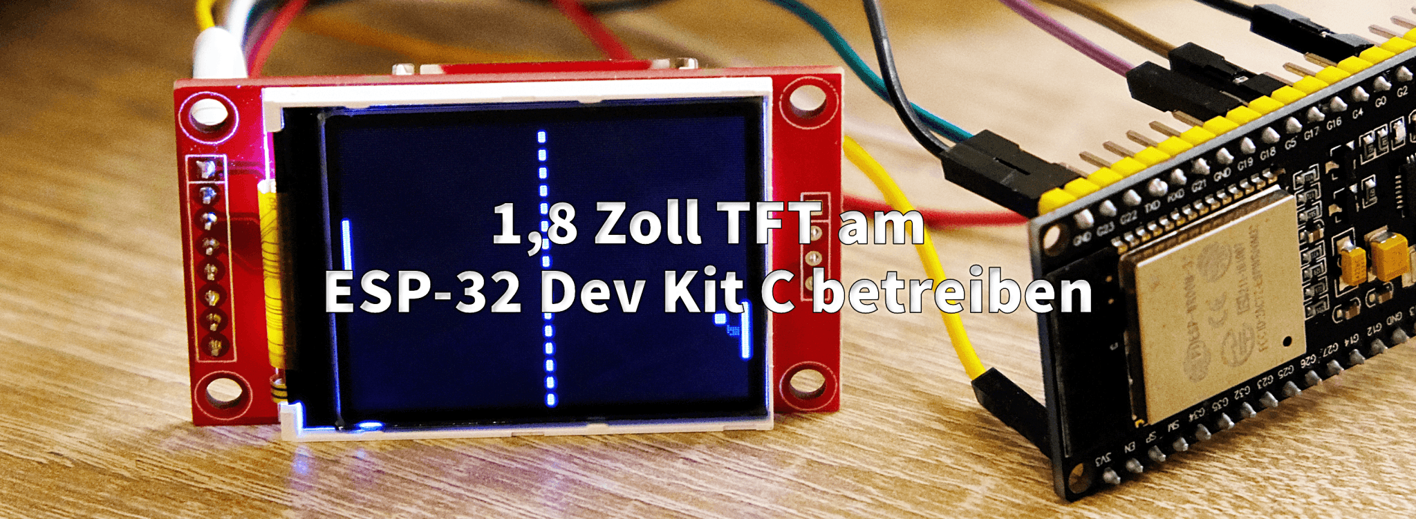
Nun können wir über das Menü "Datei" -> "Beispiele" -> "TFT_eSPI" -> "160x128" einen Beispielsketch aufrufen und ohne weitere Änderung oder Konfiguration auf unseren ESP32 laden.
Hier ein Foto des Pong_V3.ino Beispielsketches in Aktion:

Wir hoffen der heutige Beitrag hilft bei der Inbetriebnahme des TFT-Displays am ESP32 und wünschen Ihnen viel Spaß beim beim Nachbauen.


31 Kommentare
Andreas Wolter
@David: es könnte eine fehlerhafte Verdrahtung sein. Eventuell wurde auch das Display nicht korrekt initialisiert.
Für einen Test könnten Sie den Schaltkreis neu aufbauen mit so wenigen Komponenten wie möglich. Dann könnten Sie ein zweites Display gleicher Bauart hinzuziehen. Wenn das das gleiche Verhalten zeigt, ist es wahrscheinlich ein Softwareproblem. Dann würde ich von Testsketches verwenden.
Grüße,
Andreas Wolter
AZ-Delivery Blog
David
Hallo,
mein Display zeigt die untere Häfte nur “Schnee” an. Woran könnte das denn liegen?
Rafael Dellà
Sorry for the double post.
I’d need to change TFT type from ST7735_REDTAB to BLACKTAB because red and blue were switched. The tab of my screen protection is green, but green option doesn’t corrects color and insert some ood black box.
Test it with this code:
#include // Graphics and font library for ST7735 driver chip
TFT_eSPI LCD = TFT_eSPI(); // Invoke library, pins defined in User_Setup.h
void setup()
{
randomSeed(analogRead(A0));
// Setup the LCD
LCD.init();
LCD.setRotation(1);
// Clear the screen.
LCD.fillScreen(TFT_BLACK);
}
char cadena100;
LCD.setTextColor(TFT_BLACK); LCD.drawString(“Rojo”, 2, 0, 2); LCD.drawString(“Verde”, 2, 15, 2); LCD.drawString(“Azul”, 2, 32, 2); LCD.setTextColor(TFT_WHITE); tt = FPS_MSEC – (millis()-t); if( tt > 0 ) delay(tt); sprintf(cadena, “FPS: %d (delayed %d)”, 1000/(millis()-t), tt); LCD.drawString(cadena, 2, 100, 2);#define FPS (25)
#define FPS_MSEC (1000/FPS)
void loop()
{
uint32_t t = millis();
uint32_t tt;
LCD.fillRect(0, 0, TFT_WIDTH – 1, 15, TFT_RED);
LCD.fillRect(0, 16, TFT_WIDTH – 1, 15, TFT_GREEN);
LCD.fillRect(0, 32, TFT_WIDTH – 1, 15, TFT_BLUE);
}
Rafael Dellà
Arduido IDE 2.2.2
TFT_eSPI 2.5.34
It works!
Okin
…hatte auch so diverse Startprobleme mit D1 Mini ESP32 und 1.8" Display. Die TFT_eSPI Version 2.5.34 (aktuell: Dez 2023) wurde mit Fehlermeldung: missing hal/gpio_II.h abgebrochen. (Toll, wenn innerhalb eines Library Teile fehlen!) Habe die Zeile #include hal/gpio_II.h einfach ausgeklammert. Bekomme nun 2 Warnungen: … TOUCH_CS pin not defined… Mit entsprechend angepasster User_Setup.h (Original wie oben überarbeiten, nicht obige Datei kopieren, funktionier nun zumindest die Textdarstellung (noch nicht weiter getestet…) Vielen Dank an AZ-Delivery! Okin
Tomas Vicente
If arduino compiler shows errors in User_Setup.h like \342
Solution for this, is not paste code directly from web page. Edit it line by line, and works ok. (error is about unicode caracters….)
Andreas Wolter
@Peter Müller: theoretisch sollte es funktionieren. Ich gehe davon aus, dass Ihr Setup sich von dem im Beitrag unterscheidet. Ich vermute genau wie Sie, dass es an den Versionen der Bibliotheken liegt. Sie könnten versuchen, die Version des ESP Cores zu downgraden. Das wäre der Schritt, den ich als erstes probieren würde. In den Kommentaren gibt es außerdem einige Lösungsansätze.
Leider gibt es immer wieder Probleme mit Updates der Bibliotheken.
Grüße,
Andreas Wolter
AZ-Delivery Blog
Peter Müller
Nach längeren ausprobieren funktioniert nun der Programmiervorgang am ESP32 – Aber nicht mit der aktuellen Board-Verwalter-Version!!! NUR Die ältere Version v.1.0.5 funktioniert – bei anderen Versionen kommen Fehlermeldungen: “lässt sich nicht Kompilierern” oder "Fehler beim hochladen. "
Peter Müller
Seit einer Woche versuche ich ALLES , aber das Display läuft NICHT am ESP32 – Ich Bitte um eine Funktionierende
Anleitung – Vermutlich geht es nur mit einer älteren Software-Version der Bibliothek???
Vielen Dank im Vorraus
Mario Neubert
Hallo,
und danke erstmal für die ausführlichen Artikel und die interessanten Kommentare hier.
Ich habe das 1,8 Zoll TFT am “ESP-32 Dev Kit C v4” wie im Artikel beschrieben mit TFT_CS 17 zum laufen bekommen.
Ich habe dazu aber eine Verständnisfrage:
Laut Datenblatt ist der VSPI_SS, was meinem Verständnis nach TFT_CS entspricht, an GPIO5.
Dort funktioniert er aber nicht. Warum? Hat das etwas mit den “Strapping Pins” zu tun?
Andreas Wolter
Zur Info: Wir haben das Projekt aktualisiert und auf den neusten Stand gebracht. Die User_Setup.h sieht mittlerweile ein wenig anders aus und der libraries Ordner befindet sich an einer anderen Stelle.
Grüße,
Andreas Wolter
AZ-Delivery Blog
Uwe B
Hallo,
ich hatte bereits das TFT am Laufen. Nun wollte ich am Projekt weiter machen. Als erstes bekam ich beim Compilieren die Info, das TFT_eSPI unbekannt wäre. Ich habe daher ein Update der Bibliothek durchgeführt und die User_Setup.h angepasst. Trotzdem funktioniert das Display nicht mehr.
Mit der alten SW im Speicher lief das Ganze noch.
Wo kann das Problem liegen?
Danke im Voraus.
Thomas
Hallo,
wie wird denn die integrierte SD Card Reader am esp32s verbunden? Gibt es da auch ein Anschluss-Schema?
Danke
Donboy
An einem ESP32 DEV KIT /38 PIN! (Bitte hier auf die Ausführung achten) funktioniert das Display wie folgt:
#include
#include
#include
// TFT_LED // 3.3V +
// TFT_SCK // GPIO 18
#define TFT_DC 2 // GPIO 02 // (A0)
#define TFT_RST 14 // GPIO 14
#define TFT_CS 17 // GPIO 17
// TFT_GND // GND
// TFT_VCC // 3.3V +
Adafruit_ST7735 tft = Adafruit_ST7735(TFT_CS, TFT_DC, TFT_RST);
void setup() {
tft.initR(INITR_BLACKTAB);
tft.fillScreen(ST77XX_BLACK);
tft.setCursor(2,65);
tft.print(“YEAHH!”);
}
void loop(){}
Man kann es also dierkt am ESP ohne 5V betreiben! Bei den Adafruit Bibliotheken kann es zu Compile Problemen kommen → hier einfach ältere Versionen über den Bibliotheksverwalter ausprobieren (mit meiner IDE funktioniert Vers 1.7.5 bestens, die aktuelle 1.10.10 NICHT!) Sonst braucht man keine Änderungen in irgendwelchen Quell-Codes !
P.S. Nicht aufgeben, hab für die Lösung mehr intensiv mehr als eine Woche gebraucht.
tonbor
#define TFT_MOSI 23 // (SDA)
#define TFT_SCLK 18
#define TFT_CS 17 // Chip select control pin
#define TFT_DC 2 // Data Command control pin (Ao)
#define TFT_RST 14 // Reset pin (could connect to RST pin)
is working ok
Francesco Scognamiglio
Leider können Sie das Display nicht dazu bringen, mit Esp32 zu arbeiten. Es wurden zahlreiche Pins-Links in User Setup ausprobiert, aber keines der Beispiele in der Bibliothek funktioniert. Wenn jemand, dessen Display 1.8 ST7735 oder ein anderes Display, das mit ESP 32 verbunden ist, mit der TFT_eSPI Bibliothek gearbeitet hat, können Sie Details zum verwendeten Benutzer-Setup angeben?
Jörg
Hallo,
heute wurde die TFT eSPI Library aktualisiert.
leider funktioniert diese User_Setup.h jetzt bei mir nicht mehr.
Arduino IDE zeigt Probleme mit dem ESP32 Board an. (vor dem Update hat es fonktioniert).
Darauf hin habe ich die neue User_Setup.h nach Eurem Muster agepasst.
Der wichtigste Abschnitt:
// ###### EDIT THE PIN NUMBERS IN THE LINES FOLLOWING TO SUIT YOUR ESP32 SETUP ######
// For ESP32 Dev board (only tested with ILI9341 display)
// The hardware SPI can be mapped to any pins
//#define TFT_MISO 19
#define TFT_MOSI 23 // (SDA)
#define TFT_SCLK 18
#define TFT_CS 15 // Chip select control pin
#define TFT_DC 2 // Data Command control pin (Ao)
#define TFT_RST 4 // Reset pin (could connect to RST pin)
//#define TFT_RST -1 // Set TFT_RST to -1 if display RESET is connected to ESP32 board RST
_______________________________________
Die Pinbelegung habe ich aus dem Original übernommen und die Verdrahtung angepasst.
Dadurch ist der GPIO 17 am ESP32 frei und ich kann ihn für die serielle Schnittstell: U2 RX / U2 TX
verwenden.
Jason
Pourriez vus partager un User_setup.h fonctionnel pour cette article svp?
Merci
Martin
Hallo,
kämpfe schon länger mit dem TFT, jetzt aktuell mal wieder, habe PlatformIO im Einsatz, das Display wie folgt angebunden (anpassung in User_Setup.h erfolgt):
23 MOSI (SPI)
19 MISO (SPI)
18 SCK (SPI)
17 CS (CS-TFT)
2 A0 (DC?)
16 RESET (RST)
aber kein Beispiel geht, entweder es wirf Fehler beim übersetzen oder wenn es Übersetzt, geht nix an dem TFT, ausser die Hintergrundbeleuchtung.
Michael Panzer
Kann man die Helligkeit der Hintergrundbeleuchtung ändern? Es strahlt ziemlich hell im dunkeln.
Kann man das Display per Code an- und abschalten? Bei Nichtbenutzung möchte ich, das das Display aus geht und erst bei Bedarf wieder angeht.
Danke für ein paar Tips
Bernd Albrecht
Mit ihrem Kommentar bzw. ihrer Frage hat Luise Früh ins Schwarze getroffen. Hier ist offensichtlich etwas vertauscht worden. Bitte wie im eBook beschrieben den LED-Pin des Displays an 3,3 V anschließen.
Luise Früh
Ist das korrekt, dass VCC an 3,3V und LED an 5V angeschlossen werden sollen? Im Datenblatt des Displays steht das nämlich genau andersherum.
Georg Wolf
Ein wenig schlauer wird man über die Befehle wenn man sich die TFT_eSPI.h anschaut.
Walter Goegebeur
Bei mir hat es funktioniert mit folgenden Änderungen :
GND nicht links in der Mitte, sondern rechts oben am ESP
in der User_Setup.h die Zeile mit MISO zu Kommentar machen, und die Zeile mit MOSI aktivieren.
Als Board habe ich das ESP32 Dev Module ( erster aus der Liste )
Viel Erfolg
Rupp Johann
Hallo ,
Die Treibersoftware für den ESP32 mit dem TFT displayST7735 https://github.com/Bodmer/TFT_eSPI Iässt ein download nicht zu .
Danke für ihre Bemühungen
Dirk Bächer
Hallo,
leider funktioniert das bei mir nicht.
Alle Beispielsketche werfen diverse Fehler aus.
Hier der Pong Sketch
Arduino: 1.8.10 (Windows 10), Board: “ESP32 Dev Module, Disabled, Default 4MB with spiffs (1.2MB APP/1.5MB SPIFFS), 240MHz (WiFi/BT), QIO, 80MHz, 4MB (32Mb), 921600, None”
In file included from C:\Users\dbaec\Documents\Arduino\libraries\TFT_eSPI/User_Setup_Select.h:22:0,
from C:\Users\dbaec\Documents\Arduino\libraries\TFT_eSPI/TFT_eSPI.h:24, from C:\Users\dbaec\Documents\Arduino\libraries\TFT_eSPI\examples\160 × 128\Pong_v3\Pong_v3.ino:11:C:\Users\dbaec\Documents\Arduino\libraries\TFT_eSPI/User_Setup.h:163:16: error: token “�” is not valid in preprocessor expressions
#define TFT_DC 2 // Data Command control pin ^C:\Users\dbaec\Documents\Arduino\libraries\TFT_eSPI/TFT_eSPI.h:131:29: note: in expansion of macro ‘TFT_DC’
#if defined (ESP8266) && (TFT_DC == 16) ^C:\Users\dbaec\Documents\Arduino\libraries\TFT_eSPI/User_Setup.h:163:16: error: token “�” is not valid in preprocessor expressions
#define TFT_DC 2 // Data Command control pin ^C:\Users\dbaec\Documents\Arduino\libraries\TFT_eSPI/TFT_eSPI.h:140:11: note: in expansion of macro ‘TFT_DC’
#if TFT_DC >= 32 ^C:\Users\dbaec\Documents\Arduino\libraries\TFT_eSPI/User_Setup.h:163:16: error: token “�” is not valid in preprocessor expressions
#define TFT_DC 2 // Data Command control pin ^C:\Users\dbaec\Documents\Arduino\libraries\TFT_eSPI/TFT_eSPI.h:151:13: note: in expansion of macro ‘TFT_DC’
#if TFT_DC >= 0 ^C:\Users\dbaec\Documents\Arduino\libraries\TFT_eSPI/User_Setup.h:162:16: error: token “�” is not valid in preprocessor expressions
#define TFT_CS 17// Chip select control pin ^C:\Users\dbaec\Documents\Arduino\libraries\TFT_eSPI/TFT_eSPI.h:188:29: note: in expansion of macro ‘TFT_CS’
#if defined (ESP8266) && (TFT_CS == 16) ^C:\Users\dbaec\Documents\Arduino\libraries\TFT_eSPI/User_Setup.h:162:16: error: token “�” is not valid in preprocessor expressions
#define TFT_CS 17// Chip select control pin ^C:\Users\dbaec\Documents\Arduino\libraries\TFT_eSPI/TFT_eSPI.h:196:11: note: in expansion of macro ‘TFT_CS’
#if TFT_CS >= 32 ^C:\Users\dbaec\Documents\Arduino\libraries\TFT_eSPI/User_Setup.h:162:16: error: token “�” is not valid in preprocessor expressions
#define TFT_CS 17// Chip select control pin ^C:\Users\dbaec\Documents\Arduino\libraries\TFT_eSPI/TFT_eSPI.h:207:13: note: in expansion of macro ‘TFT_CS’
#if TFT_CS >= 0 ^C:\Users\dbaec\Documents\Arduino\libraries\TFT_eSPI/User_Setup.h:162:16: error: token “�” is not valid in preprocessor expressions
#define TFT_CS 17// Chip select control pin ^C:\Users\dbaec\Documents\Arduino\libraries\TFT_eSPI/TFT_eSPI.h:230:10: note: in expansion of macro ‘TFT_CS’
#if (TFT_CS >= 0) && (TFT_CS < 32) && (TFT_DC >= 0) && (TFT_DC < 32) ^Mehrere Bibliotheken wurden für “TFT_eSPI.h” gefunden
Benutzt: C:\Users\dbaec\Documents\Arduino\libraries\TFT_eSPI
Nicht benutzt: C:\Users\dbaec\Documents\Arduino\libraries\TFT_eSPI-master
Mehrere Bibliotheken wurden für “SPI.h” gefunden
Benutzt: C:\Users\dbaec\Documents\Arduino\hardware\espressif\esp32\libraries\SPI
Mehrere Bibliotheken wurden für “FS.h” gefunden
Benutzt: C:\Users\dbaec\Documents\Arduino\hardware\espressif\esp32\libraries\FS
Mehrere Bibliotheken wurden für “SPIFFS.h” gefunden
Benutzt: C:\Users\dbaec\Documents\Arduino\hardware\espressif\esp32\libraries\SPIFFS
exit status 1
Fehler beim Kompilieren für das Board ESP32 Dev Module.
Dieser Bericht wäre detaillierter, wenn die Option
“Ausführliche Ausgabe während der Kompilierung”
in Datei → Voreinstellungen aktiviert wäre.
mat-sche
Hi @ ALL,
gibt es eine Beschreibung in der alle Befehle der Bibliothek zur Ansteuerung vom Display beschrieben sind?
Würd mich über einen Link freuen!
Gerd Hofmann
Bei mir ist ebenfalls wie im Post von MIchael Brüning beschrieben die Darstellung spiegelverkehrt. Ich verwende ebenfalls das ESP 32 Developer Board und das AZ 1.8 Zoll TFT mit 128×160. Als Beispiel habe ich in der Arduino IDE “Datei → Beispiele → TFT_eSPI → 160 × 128 → TFT_Clock” ausgewählt. Kennt jemand zu diesem Problem eine Lösung?
Michael Heber
Ich habe mir die neueste ESP-Version (1.0.2) heruntergeladen, kann aber weder unter Boards den “ESP-32 Dev Kit C” noch die angegebenen Beispiele finden. Das erste ESP-Board das bei mir angezeigt wird ist das “ESP32 Dev Modul”. Wie kann ich zu einer anderen Board-Bibliothek kommen?
Michael Brüning
Bei mir läuft der Uhrzeiger verkehrt herum und die Schrift ist auch gespiegelt und somit nicht lesbar. Ich verwende von heise das ESP 32 Developer Board und das AZ 1.8 Zoll TFT mit 128×160.
flai
Ein schönes Projekt. Leider ist das Display derzeit ausverkauft. Vielen Dank für die angepasste Datei.