When I was performing the VHS holiday course "Programming Robot Cars and Remote Control", I probably learned more than the participants as the executive.
First: After the very good experiences with the IR remote control with the new Smart Car kit I wanted to realize this inexpensive solution with the easy -to -use motor Shield V1. While the kiddies were free in the afternoon, I had to struggle with difficulties that were not predicted. Result: The IR remote control works very nicely (with the limitation of sunlight) with the motor controllers L298N, L293D and Motor Shield V2, but not with the Shield V1 motor. And Motor Shield V1 works very nicely with Bluetooth HC-05, 433MHz HC-12 and 2.4 GHz NRF24L01. But Motor Shield V1 and IR cannot get along, are not compatible.
Secondly: Remote control with the Bluetooth transceiver HC-05 is also a practical and inexpensive solution, but only for those who have an Android smartphone. If you have an iPhone, you have an iPhone. A few years ago, it was said in advertising. Even Bluetooth is different. There is a Bluetooth carduino app, but pairing with the HC-05 did not work. And one participant had no smartphone at all. Result: A Bluetooth remote control without a smartphone, preferably with the joystick module, has to be developed, because even after research on the Internet several days, I have not found anything like this.
We had already assembled the Robot Car with the Bluetooth Transceiver HC-12 in the course; It works very nicely with an Android smartphone and the Arduino Bluetooth controller app. When searching for an independent remote control, the question arose whether we take a second AVR microcontroller with a second HC-05, or a microcontroller that brings a Bluetooth interface with you, e.g. an ESP32. I choose that for two reasons Lolin32. First, a small Lipo battery with 3.7V is sufficient, which can be charged via the µUSB interface and ensures the voltage supply of the micro controller during operation. Secondly, the Lolin32 comes unreactered; Instead of the pins for use on a Breadboard, I was able to solder spring strips instead, into which I was able to insert the slightly modified joystick module.
Required hardware
|
1 |
Alternatively any ESP32 |
|
|
1 |
||
|
1 |
||
|
1 |
Housing approx. 80x50x26mm |
Modification on the joystick module
All joystick modules available on the market have steered pins as in the following picture on the left. So you can neither put the module directly into a Breadboard, nor as I thought of in the spring strips on my Lolin32. Fortunately, the five -pin pinbar does not have to be drained as a whole, but with the help of the wife you can pull out the pins individually after heating the soldering point. Then pins are being soldered (right in the picture).

Here is a picture of the Lolin32 with spring strips and a small 3.7V Lipo battery. The joystick module is inserted into pins 27 to 32. On the underside I attached a flat piece of foam with carpet tape. Pinotout and eBook for the Lolin32 can be found on the Product page.

The sketches
After the Arduino Ide with the link
https://raw.githubusercontent.com/espressif/arduino-esp32/gh-pages/package_esp32_index.json
Under File/Pre -Settings in the "Additional Board Administrator" line made usable for all ESP32 and selected the Lolin32, you can access a variety of program examples:

Even if all descriptions indicate that the sketches under Bluetooth serial are designed for the connection to the smartphone, I have the hardly documented sketch by hinting on the Internet Serialoserialbtm Discovered and tinkered with it and in fact you can establish the connection between Lolin32 and an AVR microcontroller with HC-05. I have the corresponding AVR program from the Software era lamp derived.
The principle is very simple: what is entered in the top line of the serial monitor is sent via Bluetooth; What is received via Bluetooth is immediately issued in the serial monitor. After I have the right MAC address of the HC-05 in the sketch Serialoserialbtm Had entered, it worked straight away.
Here is the sketch for the Lolin32, printed in fat, my changes that you have to adapt accordingly for your hardware. (Download code)
// this example code is in the public domain (or cc0 licensed, at your option.)
// by Victor Tchistiak - 2019
//
// This example demostrates Master Mode Bluetooth Connection and Pin
// It creates a bridge between serial and classical bluetooth (SPP)
// This is an extent of the serialoserialbt Example by Evandro Copertecini - 2018
//
Bluetooth series Serialbt;
String Macadd = "98: D3: 71: F5: E7: D0"; // Mac address of the HC-05
uint8_t address[6] = {0x98, 0xd3, 0x71, 0xf5, 0xe7, 0xD0};
// uint8_t address [6] = {0x00, 0x1d, 0xa5, 0x02, 0xc3, 0x22};
String Surname = "HC-05-2"; // name of my HC-05 transceic verses
char *pin code = "1234"; // <- Standard Pin would be provided by default
Bool connected;
void set up() {
Serial.Begin(115200);
//Serialbt.setpin(pin);
Serialbt.Begin("Lolin32_94: B9: 7E: D9: 52: C6", true); // Mac address of lolin32
//Serialbt.setpin(pin);
Serial.print("The device started in master fashion, make sura remote bt device is on!");
// Connect (address) is almost (Upto 10 Secs Max), Connect (name) is slow (Upto 30 secs max) as it needs
// to resolve name to address first, but it allows to connect to different devices with the same name.
// Set coredbuglevel to info to view devices bluetooth address and device names
// Connected = serialbt.connect (name);
connected = Serialbt.connect(address);
IF(connected) {
Serial.print("Connected Succesfully!");
} Else {
while(!Serialbt.connected(9600)) {
Serial.print("Failed to Connect. Make Sure Remote Device is Available and in Range, then Restart App.");
}
}
// Disconnect () May Take Upto 10 Secs Max
IF (Serialbt.disconnect()) {
Serial.print("Disconnected Succesfully!");
}
// This would reconnect to the name (Will Use Address, IF Resolved) Or Address Used with Connect (Name/Address).
Serialbt.connect();
}
void loop() {
IF (Serial.Available()) {
intimately code = Serial.read();
Serialbt.write(code);
}
IF (Serialbt.Available()) {
Serial.write(Serialbt.read());
}
delay(20);
}
To find out the MAC address of your HC-05, do the module by pressing the button when switching on to AT-Kommando mode and entering AT+ADDR? a. You can find more details in our eBook On the product page.
It is also important for the Robot Car that the receiving HC-05 must already be switched on when this sketch is started. The display in the serial monitor is somewhat confusing. If everything works, the messages appear "Connected Succesfully!" and "Disconnected Succesfully!", however, "reconnected" becomes without further text edition. So despite the last message from the test, the connection is and you can start entering and transmission.
But - the characters are transmitted individually as a char. However, I need the transmission of a four -digit code as an integer number so that I can use it to control my motor controller.
However, I already had this problem with mine 433MHz remote control Dissolved with two HC-12 transceivers and was able to take over code fragments. The magic word means parsint ().
And I do not want to transmit an input in the serial monitor, but the code for the engine control. So the code that establishes the Bluetooth connection must be expanded to query the X and Y axis of the joystick.
Here is the extended code for determining the code using the function map (). Explanations follow. (Download code)
Bluetooth series Serialbt;
String Macadd = "98: D3: 71: F5: E7: D0";
uint8_t address[6] = {0x98, 0xd3, 0x71, 0xf5, 0xe7, 0xD0};
// uint8_t address [6] = {0x00, 0x1d, 0xa5, 0x02, 0xc3, 0x22};
String Surname = "HC-05-2";
char *pin code = "1234"; // <- Standard Pin would be provided by default
Bool connected;
void set up() {
Serial.Begin(115200);
pin mode(32,OUTPUT);
pin mode(33,OUTPUT);
pin mode(27,Input_pullup);
digital(32,Low);
digital(33,HIGH);
Serialbt.Begin("Lolin32_94: B9: 7E: D9: 52: C6", true); // Name of Device
Serial.print("The device started in master fashion, make sura remote bt device is on!");
connected = Serialbt.connect(address);
IF(connected) {
Serial.print("Connected Succesfully!");
} Else {
while(!Serialbt.connected(9600)) {
Serial.print("Failed to Connect. Make Sure Remote Device is Available and in Range, then Restart App.");
}
}
// Disconnect () May Take Upto 10 Secs Max
IF (Serialbt.disconnect()) {
Serial.print("Disconnected Succesfully!");
}
// This would reconnect to the name (Will Use Address, IF Resolved) Or Address Used with Connect (Name/Address).
Serialbt.connect();
}
void loop() {
intimately y = map(analogead(25)+100, 0, 4095, 1,9);
intimately X = map((analogead(26))+100, 0, 4095, 1,9);
Serial.print("Analogread (25) =");
Serial.print(analogead(25));
Serial.print("Analogread (26) =");
Serial.print(analogead(26));
intimately code = 1000*y+100*X;
Serial.print(code);
Serialbt.print(code);
delay(250);
}
The joystick module requires a power supply that takes place via pins 32 (-) and 33 (+). The adjacent pins 25 and 26 provide the analog values of the joystick as 12-bit numbers, i.e. value range 0 to 4095. PIN 27 is defined as an input_pullup for the joystick button, but is not used by me. As I said, with the map () function, the values are reduced from 0 to 4095 to area 1 to 9. Since the value for the middle position for me was not at 2047, but only around 1900, I increased the value of analogread by 100. It is crucial that the middle position provides the "most" value 5; The code for the idle state is 5500.
Now to the receiver side, Robot Car with AVR microcontroller, Motor Shield V1 and HC-05. (Download code)
/* Sample code for Robot Car With Motor Shield V1 and BT Receiver HC-05, AS OF 20220515
Based on Adafruit Motor Shield V2 Library, Copyright Adafruit Industries LLC
This code is public domain, enjoy!
Modified for Funduino
Pins
BT VCC to arduino 5V out.
Bt gnd to gnd
Arduino A1 = 15 (SS RX) - BT TX No Need Voltage Divider
Arduino A2 = 16 (SS TX) - BT RX Through a Voltage Divider (5V to 3.3V)
*/
AF_DCMotor Motor1(2);
AF_DCMotor Motor2(3);
// Initialize HC-05
Software Btserial(17, 18); // rx, tx over cross to tx, rx (voltage divider)
intimately X = 0;
intimately y = 0;
intimately leaf = 0;
intimately right = 0;
intimately code = 5500;
intimately code = 5500;
intimately speed = 0;
float factor = 1.8; // Correction for Speedlevel 255/100 * 6V/VBATT
void set up() {
Serial.Begin(9600); // Set Up Serial Monitor AT 9600 BPS
Serial.print("Engine sketch!");
Btserial.Begin(9600); // Set up transmission speed for HC-05
Serial.print("Softwareerial Initialized!");
} // End setup
void loop() {
IF (Btserial.Available() > 1) {
// Read serial input and convert to integer (-32,768 to 32.767)
code = Btserial.parsint();
Serial.print("Code Received:");
Serial.print(code);
IF (codeRead<=9999) {
if (code != codeRead) {
code = codeRead;
// Serial.print("code: ");
// Serial.println(code);
}
}
else {
// Serial.print("wrong code received: ");
code = 5500;
}
}
// else {
// Serial.println("Nothing received");
// code = 5500;
// }
BTSerial.flush();//clear the serial buffer for unwanted inputs
Serial.print("code: ");
Serial.println(code);
motor();
delay(200); //little delay for better serial communication and to avoid bouncing
} // end loop
void motor() {
int speedLevel[9] = { -100, -80, -60, -40, 0, 40, 60, 80, 100};
y = int(code / 1000);
x = int((code - 1000 * y) / 100);
speedL = speedLevel[y - 1];
Serial.print("code = ");
Serial.print(code);
Serial.print(" y = ");
Serial.print(y);
Serial.print(" x = ");
Serial.print(x);
Serial.print(" speedL = ");
Serial.println(speedL);
//Korrektur der Fahrtstufen für Kurvenfahrt
if (x == 1) {
right = speedL + 40;
left = speedL - 40;
}
else if (x == 2) {
right = speedL + 20;
left = speedL - 20;
}
else if (x == 3) {
right = speedL + 10;
left = speedL - 10;
}
else if (x == 4) {
right = speedL + 5;
left = speedL - 5;
}
else if (x == 6) {
right = speedL - 5;
left = speedL + 5;
}
else if (x == 7) {
right = speedL - 10;
left = speedL + 10;
}
else if (x == 8) {
right = speedL - 20;
left = speedL + 20;
}
else if (x == 9) {
right = speedL - 40;
left = speedL + 40;
}
else {
right = speedL;
left = speedL;
}
//Eingabe der Fahrtstufen für "left" und "right"
Serial.print("left = ");
Serial.print(left);
Serial.print(" right = ");
Serial.println(right);
if (left < 40 & left > -40) {
motor1.run(RELEASE);
}
if (right < 40 & right > -40) {
motor2.run(RELEASE);
}
if (left >= 40) {
if (left > 100) left = 100;
motor1.run(FORWARD);
motor1.setSpeed(left * factor);
}
if (right >= 40) {
if (right > 100) right = 100;
motor2.run(FORWARD);
motor2.setSpeed(right * factor);
}
if (left <= -40) {
if (left < -100) left = -100;
motor1.run(BACKWARD);
left = -left;
motor1.setSpeed(left * factor);
}
if (right <= -40) {
if (right < -100) right = -100;
motor2.run(BACKWARD);
right = -right;
motor2.setSpeed(right * factor);
}
} // end motor
I didn't have to make any changes to the self-defined function motor(). It takes the value of the global variable code and converts it into speed steps.
The essential lines of code for Bluetooth reception are in the void loop(). I took these code lines from an earlier project with the HC-12, but there is a difference in the structure. Since most of the digital pins are already occupied by the Motor Controller V1, the pins A0 to A5 (=D14 to D19) are suitable for the SoftwareSerial interface. However, there are two major differences to the HC-12, which we could connect directly to the analog pins: First, the pins do not provide enough current to power the HC-05 and second, the transceiver can only handle 3.3 V at the RX pin.
This problem can be solved with breadboard and cables and a voltage divider, or with a small self soldered adapter on a breadboard. Here circuit and pictures for the connection of the HC-05 to the Motor Shield V1.
This problem can be solved with breadboard and cables and a voltage divider, or with a small self soldered adapter on a breadboard. Here circuit and pictures for the connection of the HC-05 to the Motor Shield V1.
On the Motor Shield I soldered some female connectors for a secure hold and the necessary connections:

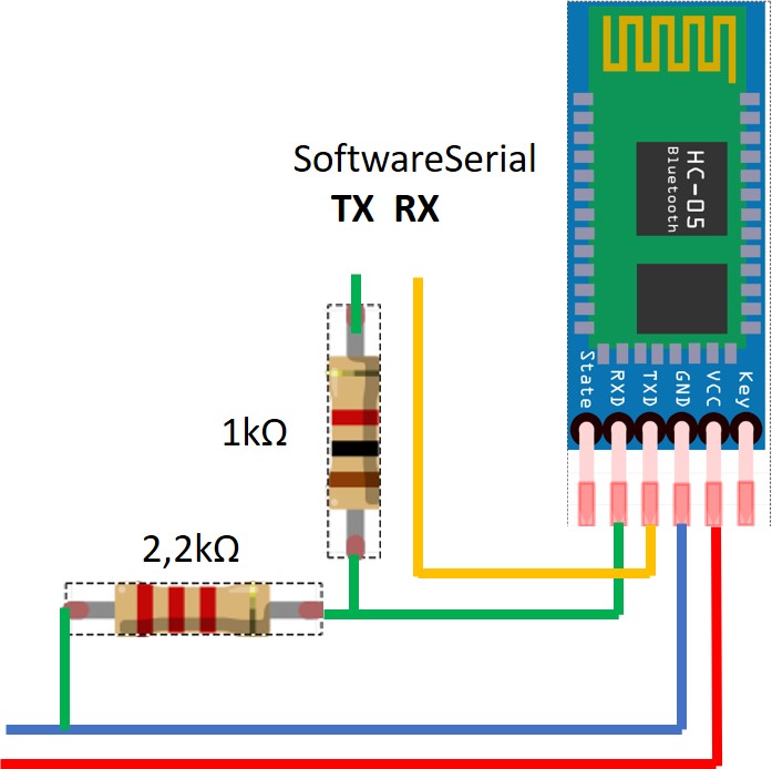
As can be seen from the HC-05's label, the supply voltage is between 3 and 5V, but the UART pins operated at 3.3V; we need a voltage divider, e.g. 1kΩ and 2.2kΩ for the RX port. Here is the circuit diagram:
Here are the pictures of the front and back of my adapter:


Here is the Robot Car with HC-05:

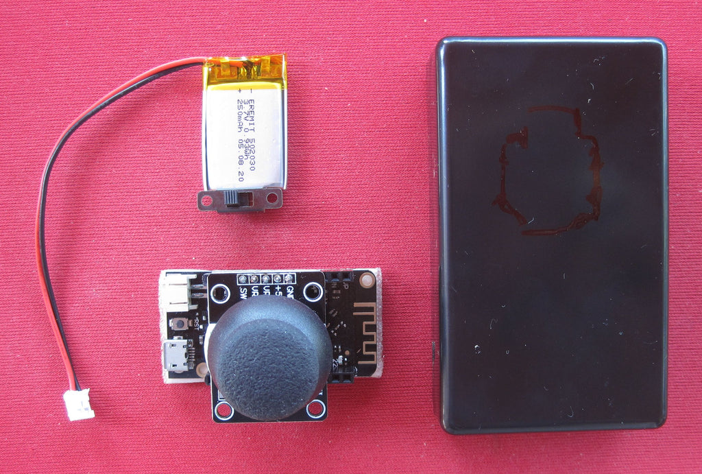
And the parts for the remote control:
And lastly, the picture of the finished Bluetooth remote control in a universal case of about 80x50x26mm-. Maybe you can also create this yourself with a 3D printer.

Have fun recreating.


1 comment
Norbert. K
Bin auf der Suche nach simplen Geschwindigkeit -und Richtungssteuerung für fernlenkbaren 24 VoltScheinwerfer mit einen Joystick 2×10 k.