The following post was sent to us by our reader Eberhard Werminghoff. Have fun reading and tinkering.
Introduction
In the previous Part 1 an e-paper display was shown in its variants and connected to the ESP32. We also abstract the structure of the software for the calendar. In one second part, We imported the flow in Node-Red and designed the output on the e-paper display. Then we "refueled" the ESP32 with the Esphome software to be able to put the display into operation.
ESP8266 D1 Mini in AZ-Touch Mod and Esphome
A reader then addressed us to show the example with an AZ touch and an ESP8266 D1 mini. The D1 Mini has too few ports so the ports that are required for loading the program are occupied by the interfaces of the display. We also began looking in the web. The Esphome developer also said there, in his statement, the RAM of the ESP8266 is too small without justifying it.
Our blogger colleague Gerald Lechner then looked at the Esphome source code. He came to the conclusion that in the file ili9341_display.cpp the calculation of the buffer with pixel width x pixel height = 240 x320 = 76800 in Getbufferlength () There are too many for the ESP8266 on the D1 mini, even if only parts of the screen are buffered. In addition, the calculation is not entirely correct, since two bytes per pixel are usually used. The conclusion is that the ESP8266 in connection with the display in AZ-Touch can only be programmed in C/C ++ via the Arduino IDE, but not with ESPHOME. Thanks to Gerald Lechner at this point.
Alternatively, I now show how our application in an AZ touch with one ESP32 is integrated.
Since appealing housing is available with the AZ touch, it is very popular. In this part we present the AZ-Touch variant, but make this ahead of parts 1 and 2 about the establishment and commissioning of Node-Red, MQTT, and ESP Home. Nothing has been changed in the parts that concern Node-Red, MQTT, and the Google calendar and are therefore still valid. We only modify the Yaml configuration file. First I explain the Yaml configuration and end with the refueling of the AZ touch.
Target presentation
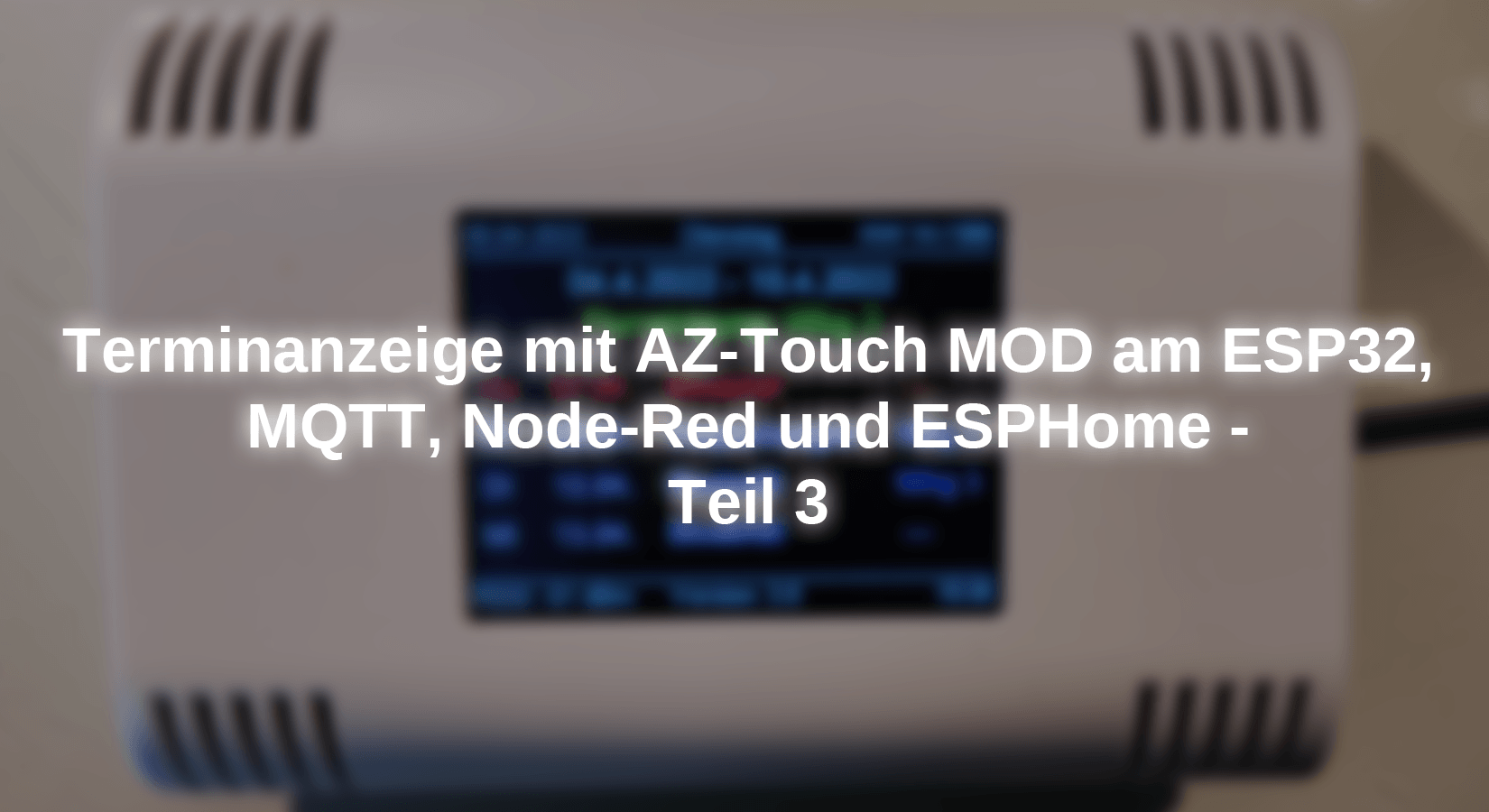
If you have worked through this 3rd part, taken over to a Yaml file, and transferred to the AZ touch display, your AZ touch looks like this:

What is different?
The AZ touch has a touch display, which consists of two components: on the one hand from a TFT screen from Nextion with an ILI9341 chip and on the other hand from the associated touch controller with an XPT2046 chip.
There is the AZ touch in the versions with a 2.4-inch or 2.8-inch screen diagonal. This post deals with the 2.8-inch variant. Special features of the 2.4-inch version only exist in the X and Y information on the display coordinates. The TFT screen is controlled via an SPI interface. I didn't change anything on the AZ touch "wiring". For those of you who want to recreate this post with individual components, I have presented a "virtual cabling" with the table below.
The following table shows the internal links of the AZ touch between the components Nexion Display and ESP32.
|
Nexion |
ESP32 |
use |
|
T_irq |
GPOI2 |
Touch controller |
|
T_do |
GPIO19 |
Touch controller connected to miso |
|
T-ilin |
GPIO23 |
Touch controller connected to Mosi |
|
T_CS |
GPIO14 |
Touch controller (chip select input) |
|
T_clk |
GPIO18 |
Touch Controller (External Clock Input) |
|
Sdo (miso) |
GPIO19 |
Spi (Master input, Slave Output) |
|
LED |
GPIO15 |
Control of the backlight |
|
Sck |
GPIO18 |
SPI (Serial Clock) |
|
SDI (Mosi) |
GPIO23 |
Spi (master output, slave input) |
|
D/C |
GPIO4 |
n / A. |
|
Reset |
GPIO22 |
n / A. |
|
CS |
Gpio5 |
Spi (chip select) |
|
Gnd |
Gnd |
Gnd |
|
VCC |
3V3 |
3V3 |
There are some interfaces that have been called twice, these are connected internally on the board.
The above means that we have to take care of the areas of Deep Sleep, display (with ILI9341) and touch controller (XPT2046), and screen saver.
The file iLi9341_esp32.yaml
The file ili9341_ESP32.yaml Contains the configuration for our project and can here be downloaded. I go through the entire file in steps and explain the individual sections. By section I mean the terms that stand in the file on the far left - i.e. without indentation. Please remember that hierarchical engagement follows strict rules. Always use 2 spaces but do not use tabulators!
Esphome
In this section, the Surname: and the information under Platformio_Options: are added.
Esphome
SurnameILI9341_ESP32
platformESP32
boardNodemcu-32S
platformio_options
upload_speed921600
monitor_speed115200
logger
This section is unchanged compared to the previous variant. By omitting the information info, further information would be transmitted about the serial interface.
logger
levelINFO
wifi
The term "! Secret" indicates the "Secrets.yaml" file in the same directory in which the associated access data can be found. You can also enter the safety-relevant data directly here. For example: off! Secrets wifi_ssid becomes SSID: "Testwan"
wifi
SSID! Secret wifi_ssid
password! Secret wifi_password
Fast_Connecttrue
power_save_modenone
output_power20dB
MQTT
Here, too, nothing important has changed compared to part 2. When the AZ touch is switched off, the broker (MQTT) sends over will_message: on the Topic: specified path Payoad: stored message. Likewise, if the AZ touch is put back into operation: birthday_message: Will be on the under Topic: stored path under Payoad: Submit the stored message. With the MQTT-Explorer you can watch the news.
mqtt
broker! Secret mqtt_ip
username! Secret mqtt_user
password! Secret mqtt_password
IDmqtt_client
birthday_message
topicILI9341_ESP32/Topic
Payoad'I am online'
will_message
topicILI9341_ESP32/Topic
Payoad'I'm off!'
Time
In this section, the current time is fetched by Timeservers and later displayed on the display at the bottom right. In contrast to the hourly update of the epaper variant, the current time is displayed here. The three URLs are optionally triggered, depending on which one can be reached.
time
platformSNTP
IDSNTP_TIME
timezoneEurope/Berlin
server
0.pool.ntp.org
1.Pool.ntp.org
2.Pool.ntp.org
Sensor
The sensors whose result is a numerical value are below the sensor section. In this project, you will only find the field strength of the incoming WiFi signal in DBM
sensor
#RSSI Based on Mac-Address ESP32
platformwifi_signal
Surname"WiFi Signal Sensor"
Update_interval30s
IDrssi_value_dsp
Text_Sensor
As the name suggests, the section Text_Sensor: all non-numerical and non-Bool sensors can be found.
Text_Sensor
#Aktueller day of the year
platformtemplate
Surname"Day of the year"
lambda-
auto doy = id (sntp_time) .now (). StrtFime ("%j");
return Doy;
IDTPL_DOY
Update_interval10s
Text sensor "hours minutes"
In this sensor, the first step is Time: (ID: SNTP_TIME) determined as a time temple and then converted into a readable format.
Text_Sensor
...
platformtemplate
Surname"Hours minutes"
lambda-
auto time = id (sntp_time). now (). StrtFime ("%H:%M");
return time;
IDTPL_HOUR_SEC
Update_interval5S
Text sensor: MQTT reception data
In these sensors, all the necessary data received by the MQTT broker are in an ID: saved. You will be needed for the display at a later date.
The sensor is just a pattern of 22 sensors for MQTT.
Text_Sensor
...
platformmqtt_subskribe
IDcalendar week
topic/SmartHome/display/calendar week
Font
To present characters and digits on a display, the corresponding information must be provided in the form of a character set.
font
file'fonts/arial.ttf'
IDfont1
size15
glyphs
'&' '@' '!' ',' '.' '?' '"' '%' '(' ')' '+' '-' '_' ':' '°' '0'
'1' '2' '3' '4' '5' '6' '7' '8' '9' 'A' 'B' 'C' 'D' 'E'
'F' 'G' 'H' 'I' 'J' 'K' 'L' 'M' 'N' 'O' 'P' 'Q' 'R' 'S'
'T' 'U' 'V' 'W' 'X' 'Y' 'Z' ' ' 'A' 'B' 'C' 'D' 'e' 'F'
'G' 'H' 'I' 'J' 'K' 'L' 'M' 'n' 'O' 'P' 'Q' 'r' 'S' 'T'
'U' 'V' 'W' 'X' 'Y' 'Z''Å' 'Ä' 'ä' 'Ö' 'Ö' 'Ü' 'ü' '/'
These sign rates are in TTF files in the "Fonts" folder and are stored in TTF format.
Windows users can find the symbols in the directory: "C: \ Windows \ Fonts". Copy the required sign rates into the "Fonts" directory below "Esphome". There are configurations on Glyphs: do without, but only the pure ASCII sign rate will be available. The German language also knows umlauts, so you have to list all the signs you use in the way specified above. You must create such a configuration for each character set to be used.
The font Have you configured now, now we are coming to font size. Do you want the font Arial in the Font sizes Use 15 and 18 pixels, you need two different entries below font:
font
file'fonts/arial.ttf'
IDfont1
size15
glyphs
.......
file'fonts/arial.ttf'
IDfont3
size18
glyphs
...........
Color
Our e-paper display from parts 1 and part 2 only knew black or white. The TFT display now used naturally has the option of portraying fonts in color. However, the colors to be used must be under color: To be defined.
color
IDmy_red
red100%
green0%
blue0%
IDmy_grey
red70%
green70%
blue70%
IDmy_yello
red100%
green100%
blue0%
We can later address the defined colors under the ID name (e.g. my_red). The colors are given classic in RGB format in "%".
Output
The TFT display has a backlight that is controlled via PIN 15 of the ESP.
output
platformLEDC
pin code15
IDgpio_15_Backlight_pwm
platformGPIO
pin code15
IDGPIO_BACKLIGHT_OFF
invertedyes
Under Platform: LEDC an LEDC PWM channel is defined as an output. Platform: GPIO Defines a GPIO as an outcome, and an inverting of the output is also requested.
Light
This part controls the output of the backlight on the GPIO15 with the ID: GPIO_15_Backlight_PWM. The condition on_turn_off: is about that off Triggered and switches back to 20s. Note that in the chapter before that Inverted: on yes stands. As a result, a turn_off switch on the LED of the backlight for the 20s.
light
platformMonochromatic
outputgpio_15_Backlight_pwm
Surname"Touch display light"
IDBack_light
restore_modeAlways_off
on_urn_off
that
delay20s
light.urn_on
IDBack_light
SPI
Now it goes to the SPI interface of the display.
# For ESP32
spi
clk_pin18
mosi_pin23
miso_pin19
IDili9341_spi
The classic SPI interface only knows the three above. The identifier
ID: ILI9341_SPI will take over this description of the interface for the following definition.
Display
display
platformIli9341
modelTft_2.4
spi_idili9341_spi
cs_pin5
dc_pin4
auto_clear_enabledtrue
Update_interval20s
reset_pin22
rotation90
lambda-
Platform: Ili9341 defines the positions to be configured. What is absolutely necessary (request) and what can be given optionally is here to find.
Model: only knows two descriptions, either a TFT display with a diagonal of 2.4 inches or the display of the M5stack. Although we use a 2.8-inch display, we can use the TFT_2.4 model, since the 2.8 variant is also operated with an ILI9341. We use the display in landscape format and now have 320x240 pixels. When positioning elements in your projects, you must observe and adapt the number of displays.
spi_id: Here we use the SPI definition with the ID: ILI9341_SPI from the previous chapter and integrate it into the display: Definition.
auto_clear_enabled: Understandable that we reset the display when switching it on, so: true
Update_interval: The display is updated every 20s.
rotation: You can hereby tell the display whether you want to operate it up or crossed. We turn the display by 90 ° and receive a display in landscape format. If we turn to 180 °, the representation becomes upright and faulty, at 270 the display is on the head - so back to 90 °.
Lambda: In the previous 2nd part, I had already pointed out that there is the possibility in ESPHOME to put C ++ code in. I, therefore, limit myself to the possibilities that I used here. Let's consider the line:
IT.print(8, 90, ID(font3),ID(red),ID(weekday1).state.C_STR());
it.print Describes the action, there is formatting information behind it. In general, the formatting could be specified as follows:
(X value of the display, Y value of the display, font, font color, displayed value)
The X-value can only adopt values that result from the width of the display. The Y-value depends on the height of the display. For font and font color, the ID () is called. The value for the day of the week must be formatted because it cannot be used in the form supplied by the MQTT broker.
IT.printf(160,239, ID(font1),Textalign :: Bottom_Center, "Version: 2.0");
The possibilities are very comfortable under it.printf (). The specification of the X/ Y value is used for specifying Textalign:: as a starting point. This is followed by either TOP_ or Bottom_ (top or bottom). The following font is based either on an imaginary line above the writing or a line below. In addition, the written orientation is related to the specified point. The written orientation is left (LEFT) or right-very-bundle (right) or centered (center). In addition, there is an extensive formatting of the values to be presented. Take a look at the function Printf () of the C library.
XPT2046
This section is part of the touch decoder. When touched, this delivers the high and legal values of the touched point. The aim of the screen saver is to avoid burning the screen. The danger is given here because information is always displayed in the same places and stop there.
XPT2046
IDtouchscreen
cs_pin14
irq_pin2
Update_interval50ms
Report_interval1s
threshold400
dimension_x320
dimension_y240
calibration_x_min256
calibration_x_max3839
calibration_y_min180
calibration_y_max3640
swap_x_yyes
on_state
lambda-
if (touched)
ESP_LOGI ("Cal", "X =%d, y =%d, x_raw =%d, y_raw =%d",
id (touchscreen) .x,
id (touchscreen) .y,
id (touchscreen) .x_raw,
id (touchscreen) .y_raw
);
auto call = id (back_light) .turn_off ();
call.perform ();
Usually the screen would have to be calibrated. Since we wake it out of sleep by simply tapping the display, it is irrelevant at which point we press. The entire screen is active.
Upload the program
Certain requirements must be met for uploading:
- Esphome is installed (Part 1)
- You have already imported the flow to Node-Red and imported the Google calendar (Part 2).
Now switch to the directory you have set up for Esphome:
 C: \> i:
 I: \>CD Esphome
 I: \ Esphome>
Then open the file ili9341_ESP32.yamlThe you here can download. Edit all with! Secret containing lines. An example explains:
Out of
SSID! Secret wifi_ssid
becomes:
SSID"Sample WLAN"
Finally, do not forget to save. Now connect the AZ touch to the USB interface and start conversion to the line:
I: \ Esphome> Esphome Run Ili9341_ESP32.YAML
Be patient! Depending on the computer, it can take some time. Then the following lines show:
 ==============00==== [Success] Took 25.38 seconds =============================
 ← [32minfo successfully compiled program. ← [0m
 Found Multiple options, please Choose One:
   [1] COM13 (Silicon Labs CP210X USB to Uart Bridge (Com13))
   [2] COM3 (HP HS2340 HSPA+ Mobile Broadband Module Device Management (Com3))
   [3] COM4 (HP HS2340 HSPA+ Mobile Broadband Module Device Management (Com4))
   [4] COM5 (HP HS2340 HSPA+ Mobile Broadband Module Modem)
 (Number):
Select the number "[1]". When you see these or similar looking lines, the software has been uploaded.
 ← [32minfo successfully uploaded program. ← [0m
 ← [32minfo Starting Log Output from Com13 with Baud Rate 115200← [0m
 [19:28:19][I] [Logger: 214]: Log initialized
 [19:28:19][I] [App: 029]: Running Through Setup () ...
 [19:28:20][I] [Wifi: 245]: WiFi Connecting to 'Buewlan'...
 [19:28:22][I] [Wifi: 502]: WiFi Connected!
 [19:28:22][I] [MQTT: 175]: Connecting to mqtt ...
 [19:28:22][I] [MQTT: 215]: MQTT Connected!
 [19:28:22][I] [App: 062]: Setup () Finished Successfully!
 [19:28:22][I] [App: 102]: Esphome version 2022.1.1 Compiled on Apr6 2022, 19:20:06
If the screen saver has reached and you reactivate the display by tapping, you will see a line that resembles it here:
[20:40:28][I] [CAL: 306]: X=161, y=128, X_RAW=2175, y_raw=1928
There are the X/Y coordinates of the point on the screen that you have tapped. X_RAW and y_raw If the screen is required for calibration, we are not interested in here. This should show the display the intended information. Congratulations!
Possible error
After the first commissioning of the AZ-Touch Mod, the screen showed nothing but a bright light. After a long search, I noticed that the ESP32 was not deep enough in the base. The soldering points of the base strip of the D1 mini were too high and prevented a correct seat in the base on the other side of the board. After I knacked the soldering points a little, the display ran flawlessly.
Conclusion
You have now pursued an excursus about Esphomas and hopefully found that a simple tool for displaying data was given to you in the interaction node -Red -> MQTT -> ESPHOME. Even if you want to display data from other systems (e.g. from a homes server), the use of MQTT and this ESPHOME display is a very good solution. Contents that are constant over a longer period of time are suitable for an e-paper display. Short-lived data to be displayed are more for a TFT display, as it was presented here.


6 comments
Andreas Wolter
@Ralf: könnten Sie beschreiben, wie Sie die Datei einspielen und mit welchen Versionen? Da das Programm bereits funktionierte, wäre es nun wichtig zu wissen, was verändert wurde. Der Hinweis von @Rainer sollte auch berücksichtigt werden. Wir haben die YAML Datei noch nicht verändert.
Grüße,
Andreas Wolter
AZ-Delivery Blog
Ralf
Die Datei aus dem Download lässt sich nicht mehr einspielen. Vielleicht könnte das der Ersteller nochmal nachbauen und entsprechend anpassen?
Rainer
Display :
Ich habe den Fehler gefunden.
In meiner …yaml-Datei war im Sektor Display angebgeben:
“reset_pin: GPIO16”
richtig ist:
“reset_pin: 22”
Bitte ggf. die Download Datei berichtigen.
Rainer
ich habe ein Problem mit der Anzeige:
Der Bildschirm wird nur weiss, zeigt keine Linien oder Zeichen an.
Der unter dem Punkt Fehler beschriebene Vorgang trifft nicht zu. Ich habe aus meinem 2. Touch den mit einem anderen Programm beschriebenen ESP32dev genommen. Da geht es.
Der weisse Bildschirm geht nach 20 Sek. in den Schlaf, wird dunkel. Er lässt sich wieder wecken, es zeigt aber nur einen weissen Bildschirm an.
Die serielle Schnittstelle zeigt den Touch richtig an :
“[I][cal:312]: x=205, y=85, x_raw=1533, y_raw=2405”
Kann mir jemand einen Tip zur Lösung geben?
Andreas Wolter
danke für den Hinweis. Wurde korrigiert.
Andreas Wolter
AZ-Delivery Blog
Rainer
Fehler in Zeile 153 : – file: “gfonts://Whisper”
richtig : – file: ‘fonts/arial.ttf’