
Dieser Beitrag beschreibt den Bau eines einfachen Thermometers mit einem DS18B20 Sensor. Wir verenden ein Board mit ESP8266-E12 und integriertem OLED Display und einen Sensor DS18B20 ohne Board. Die Schaltung ist sehr einfach und der Sensor kann direkt mit dem Board verlötet werden.
Schaltung:

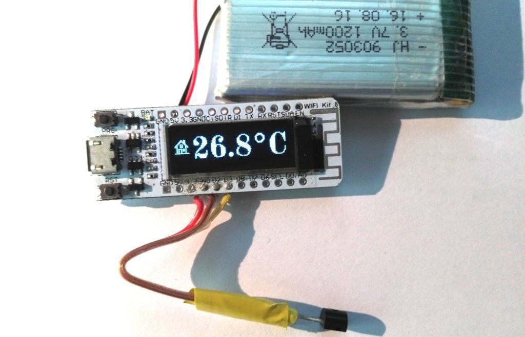
Ansicht:

Da der ESP8266 WiFi unterstützt habe ich im Sketch bereits die Unterstützung eines zweiten entfernten Sensors eingebaut. Dieser zweite Sensor wird mit dem Thermometer mit ESP-Now kommunizieren, ein Protokoll mit dem sehr energiesparende Lösungen geschaffen werden können. Die Messergebnisse werden dann abwechselnd am Display angezeigt. Wenn kein entfernter Sensor angeschlossen ist, wird nur der Wert des internen Sensors angezeigt.
Der Sketch ist ausführlich kommentiert.
Sketch:
/* Esp8266 mit OLED Display als Thermometer
 */

//Bibliotheken für WiFi
#include <ESP8266WiFi.h>
//Bibliothek für OLED Display
#include <U8g2lib.h>
//Bibliotheken für DS18B20 Temperatur Sensor
#include <OneWire.h>
#include <DallasTemperature.h>

//Bibliothek für ESP-Now
extern "C"{
#include <espnow.h>
}

//Pins für Temperatursensor
const byte bus = 0;//pin GPIO0

//Protokoll zum Auslesen  des Sensors
OneWire oneWire(bus);

//Sensor Instanz
DallasTemperature sensoren(&oneWire);

//Array um Sensoradressen zu speichern
DeviceAddress adressen;

//Display initialisieren
U8G2_SSD1306_128X32_UNIVISION_F_SW_I2C u8g2(U8G2_R0, /* clock=*/ 5, /* data=*/ 4, /* reset=*/ 16);

//Offset zur Kalibrierung der Temperatur
const uint8_t offset = 15;

//Werte der Temperatursensoren -127 = der Wert,
//den man erhält wenn kein Sensor angeschlossen ist
  float aussen = -127;
  float innen = -127;

// Nach einem Reset ist die SSID sichtbar damit ein entfernter Sensor sich
// verbinden kann. Nach ca. 2 Minuten sollte die SSID versteckt werden
// Zähler zum Abschalten der sichtbaren SSID
int cnt = 24;

//Logos als Bitmap für Display
#define haus_width 16
#define haus_height 16
static unsigned char haus_bits[] = {
   0x80, 0x0c, 0xc0, 0x0d, 0x60, 0x0f, 0x30, 0x0e, 0x18, 0x0c, 0xcc, 0x19,
   0x46, 0x31, 0x47, 0x71, 0xc5, 0x51, 0x04, 0x10, 0xf4, 0x16, 0x94, 0x16,
   0x94, 0x16, 0x94, 0x10, 0x94, 0x10, 0xff, 0xff };

#define baum_width 16
#define baum_height 16
static unsigned char baum_bits[] = {
   0x00, 0x00, 0x00, 0x00, 0xe0, 0x01, 0x10, 0x05, 0x08, 0x0a, 0x34, 0x13,
   0x04, 0x10, 0x02, 0x10, 0x02, 0x08, 0x04, 0x16, 0x18, 0x10, 0xd0, 0x17,
   0xa0, 0x09, 0x80, 0x01, 0x80, 0x01, 0xff, 0xff };


//Datenstruktur für den Datenaustausch über ESP Now
struct DATEN_STRUKTUR {
    float temp = 0;
};

//Netzwerk Name
char* SSID = "Thermometer";


//Callback funktion wenn Daten empfangen wurden
void on_receive_data(uint8_t *mac, uint8_t *r_data, uint8_t len) {

    DATEN_STRUKTUR data;
    //wir kopieren die empfangenen Daten auf die Datenstruktur
    //um über die Datenstruktur zugreifen zu können
    memcpy(&data, r_data, sizeof(data));
    aussen = data.temp;
  };

// function um eine Sensoradressen zu drucken
void printAddress(DeviceAddress adressen)
{
  for (uint8_t i = 0; i < 8; i++)
  {
    if (adressen[i] < 16) Serial.print("0");
    Serial.print(adressen[i], HEX);
  }
}

void setup() {
  Serial.begin(115200);

  WiFi.begin();
  //Konfiguration des Access Points
  WiFi.mode(WIFI_AP);

  WiFi.softAP(SSID);
  //ESOP-Now initialisieren
  if (esp_now_init()!=0) {
    ESP.restart();
    delay(1);
  }


  // ESP Rolle festlegen 1=Master, 2 = Slave 3 = Master + Slave
  esp_now_set_self_role(2);
  //und callback funktion registrieren
  esp_now_register_recv_cb(on_receive_data);

  //Display vorbereiten
  u8g2.begin();
  u8g2.enableUTF8Print();
  u8g2.setFontMode(0);

  //Temperatursensor initialisieren
  sensoren.begin();
  Serial.print(sensoren.getDeviceCount(), DEC);
  Serial.println(" Sensoren gefunden.");
  //Nun prüfen wir ob der Bus im parasitären Modus ist
  Serial.print("Parasitärer Modus ist ");
  if (sensoren.isParasitePowerMode()) {
    Serial.println("EIN");
  } else {
    Serial.println("AUS");
  }
  //Nun prüfen wir ob einer der Sensoren am Bus ein Temperatur Sensor ist
  if (!sensoren.getAddress(adressen,0)) {
    Serial.println("Kein Temperatursensor vorhanden!");
  }
  //adressen anzeigen
  Serial.print("Adresse: ");
  printAddress(adressen);
  Serial.println();
  sensoren.setResolution(adressen,12);
  Serial.print("Auflösung = ");
  Serial.print(sensoren.getResolution(adressen), DEC);
  Serial.println();
  //Pullup Widerstand für Temperatursensor
  pinMode(0,INPUT_PULLUP);
}

void loop() {
  char text[50] = {0}; //Textbuffer für Display
  int tmp; //Temporär für Temperaturen
  sensoren.requestTemperatures(); // Sensor  Messung starten
  delay(800);//Zeit um die Temperatur zu messen
  innen = sensoren.getTempC(adressen); //Temperatur vom Sensor lesen
  //Wir wandeln die Temperatur nach integer mit einer Dezimalstelle
  tmp = round(innen * 10);
  //Ausgabetext generieren
  sprintf(text,"%2d.%01d°C", tmp/10-offset, abs(tmp%10));
  //und an Display senden
  u8g2.firstPage(); do {
    //zuerst das Logo
    u8g2.drawXBM( 0, 8, haus_width, haus_height, haus_bits);
    //dann den Text
    u8g2.setFont(u8g2_font_osb26_tf);
    u8g2.setFontDirection(0);
    u8g2.drawUTF8(20, 30, text);
  } while ( u8g2.nextPage() );
  delay(5000); //5 Sekunden warten
  //Zähler vermindern
  if (cnt > 0) cnt--;
  //Haben wir einen Wert von einem entfernten Sensor
  //Dann zeigen wir den an
  if (aussen !=  -127) {
    //Wir wandeln die Temperatur nach integer mit einer Dezimalstelle
    tmp = round(aussen * 10);
    //Ausgabetext generieren
    sprintf(text,"%2d.%01d°C", tmp/10, abs(tmp%10));
    //und an Display senden
    u8g2.firstPage(); do {
      //zuerst das Logo
      u8g2.drawXBM( 0, 8, baum_width, baum_height, baum_bits);
      //dann den Text
      u8g2.setFont(u8g2_font_osb26_tf);
      u8g2.setFontDirection(0);
      u8g2.drawUTF8(20, 30, text);
    } while ( u8g2.nextPage() );
    delay(5000); //5 Sekunden warten
    //Zähler vermindern
    if (cnt>0) cnt--;
  }
  //Wenn Zähler auf 0 die SSID verstecken
  if (cnt <= 0) WiFi.softAP(SSID,NULL,1,1);
}
Mit einem geeigneten LiPo-Akku mit 3.7 V kann das Thermometer mit Batterie betrieben werden. Laderegler und Batteriebuchse sind am Board vorhanden.


16 comments
Gerald Lechner
Vielen Dank!
Die Buchse für den Akku an der Untrerseite der Platine ist ein 1.25mm JST 2.
Rahul
Tolles Projekt!
Von dem Aufbau habe ich ein System mit DS18B20 und eins mit DHT22 aufgebaut.
Die loggen ihre Temperatur- (und Feuchte-) Werte auf einem Intranet-Webserver.
Um welchen Steckverbinder handelt es sich bei dem Akku-Anschluss?
Bernd Albrecht
Die eingebaute LED ist die Lade-Kontrollleuchte für einen LiPo-Akku. Rot = laden, grün = laden fertig, rot-blinkend = kein Akku und dunkel = geladener Akku. Diese LED kann nicht abgeschaltet werden.
AndreasD
Hallo,
kann mir jemand helfen, wie ich die Onboard-LED abschalte? Ich weiß nicht, warum ich mich so anstelle. Bei mir blinkt sie sehr schnell. Im Sketch habe ich allerdings nichts gefunden.
Danke für eine Antwort.
Andreas
István Maszlik
Hallo! Ich kann die externen und internen Thermometer nicht anschließen. Wie richte ich es ein?
Carsten Jürges
Man könnte das noch um die Luftfeuchtigkeit (bme280) erweitern.
Weiterhin habe ich einen Balken spendiert, der anzeigt, wie alt die Messung vom Aussensensor ist. Ist diese zu alt, setze ich den Wert wieder zurück, damit dessen Anzeige unterdrückt wirdWas interessiert eine Temperatur von vor zwei Stunden …
Wenn der Wert sehr alt ist, lasse ich dieses Thermometer im WiFi sichtbar werden, damit sich das Aussenthermometer neu verbinden kann …
Mario Spies
Guten Tag,
ist es möglich das Board mit ESPEASY zu betreiben?
An welchen I/O Ports hängt das Display.
Michael Riedel
Hallo ich bin neu Hier ,
versuche seit Tagen das kleine Projekt zum laufen zu bringen und verzweifle ….
beim überprüfen bleib es hier hängen
#include
Meldung “no such file oder Directory”
wo kann ich und welche Libary " espNow " herunterladen ???
habe schon vieles versucht ohne Erfolg
beim anstecken des ESP 8266 steht auf dem Display 10 nets found
wer kann mir helfen ??
mfG Michael
Helmut Riethmeier
Warum gibt es bei den Kommentare keine Antworten zu lesen, werden die Antworten nur über Email verschickt.
Gruß Helmut
AndreasD
Hallo,
ich bin neu hier und dementsprechend nicht der Profi. Das Projekt finde ich sehr gut. Meine erste Frage ist, warum ist bei
esp_now_set_self_role(2);
standardmäßig Slave eingestellt?
Die zweite Frage: Wann nutze ich (3) Master & Slave und wann (1) Master?
Und drittens: Wenn ich einen Aussensensor mit dem ‘Master’ verbinden möchte, was trage ich dann beim Master ein, (1) oder (3)? Und wenn ich es richtig deute, dann trage ich bei dem zweiten (2) ein. Wie viele könnte ich an den Master anmelden?
Viertens: Wenn ich einen Aussensensor habe, der kein Display benötigt, kann ich dann auch einen esp8266 ESP01S WLAN nutzen? Was müsste dann im Code geändert werden?
Ich bin dankbar für jeden Hinweis.
Beste Grüße, Andreas
Thomas
Hallo.
Super Projekt. Ich hätte allerdings 2 Fragen.
1. Was stellt die Schaltung im ersten Bild dar? Die mit dem 10 kOhm Widerstand?
2. Warum ein Temperaturoffset von 15? Wozu ist das Offset gut?
Ich habe das Offset auf 0 gestellt, nun zeigt mir das Thermometer die richtige Temperatur an.
Vielen Dank.
Grüße, Thomas
Gerald
Ein 1200mAh Akku hält ohne Aufladung ca. 1 Tag.
Der 4.7 kOhm Widerstand ist nicht nötig wenn man den Datenpin mit pinMode auf INPUT_PULLUP setze.
Für einen Temperatursensor der dei Daten mit WiFi und mit Batterie betrieben werden kann, möchte ich auf den nächsten Beitrag in diesem Blog verweisen.
Sören
Meines Erachtens fehlt zwischen Plus-Pol und Daten-Pin ein 4,7kOhm Widerstand – oder ist der bei 3.3V nicht nötig?
Ich arbeite grundsätzlich mit 5V.
Passende Widerstände sollte az-delivery auch anbieten…
Stephan
Hallo Manuel,
du könntest die Temperaturen mit MQTT versenden. Für OpenHab gibt es da dann entsprechende Unterstützung.
Nutze ich auch für diverse Sensoren. Z.B.: https://github.com/stritti/smart-swimming-pool
Ralph
Das mit der Batterie würde mich auch interessieren.
Zu. Kühlschrank, der ist ein relativ guter Farradayscher Käfig mit Wifi innen ist da nicht viel. Funfakt deswegen hatte Snowden als die Journalisten ihn in HongKong aufsuchten, deren Smartphones in den Kühlschrank gesteckt.
Manuel
Hi,
interessante Sache. Wie lange würde die Batterie in etwa halten? Und wäre das WiFi geeignet, um den Sensor im SmartHome (openHAB) zu integrieren? Suche noch eine Lösung um die Kühlschranktemperatur zu überwachen.
Danke für Kommentar.
Grüße
Manuel