
We always want to create a perfect climate for our plants in the garden or greenhouse. Sometimes, however, we may forget to pour them and that has undesirable consequences for the plants, especially in hot weather.

With this project that you can also adapt to your needs, we will be able to deal with our plants a little more relaxed, since the irrigation is completely autonomous and in the event of heat and excessive moisture, the air in the greenhouse is renewed.
We will use the soil moisture sensor with irrigation warning. This reads the soil moisture value in order to activate the automatic irrigation. This happens by activating an electrical style (for example). We will also use a moisture and temperature sensor to record these environmental parameters. All data is then displayed on a TFT screen.
Required materials
- Floor alarm moisture sensor plant irrigation module
- MB 102 Breadboard Kit - 830 Breadboard, power supply adapter 3.3V 5V, 65Stk plug -in bridges
- Jumper Wire Kabel 40 pc. 20 cm f2m female to times each
- Microcontroller Board Atmega328 with USB cable
- DHT11 BREAKOUT Module with board and cable temperature sensor and air humidity sensor
- 1.8 inch Spi TFT Display 128 x 160 pixels
- PCA9548A I2C IIC Multiplexer
- 4-relay module 5V with optocoupler low-level trigger
- Active mini fan
Required software
- Arduino IDE
- ino sketch
- Wire library (wire.h) (integrated)
- Spi Library (Spi.H) (integrated)
- TFT Library (Tft.H) (library administrator)
- Library for DHT-11 sensor (DHH.H) (library manager)
Circuit and description of the modules used
Download of the circuit diagram
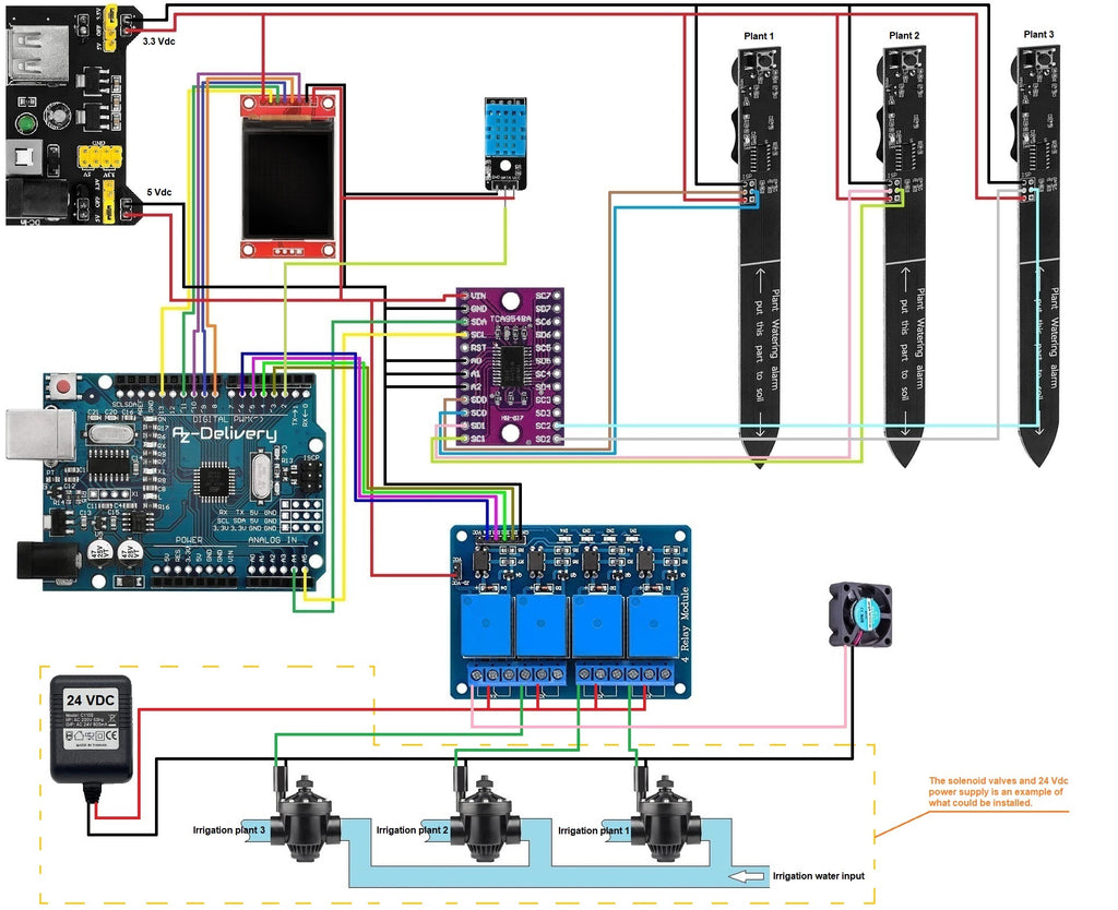
The main idea of this project is to the moisture of the soil of our plants by the Soil moisture sensor and, in the case of the building of a greenhouse, the moisture and the temperature of the surroundings with the DHT-11 sensor to eat. The data obtained should be on the 1.8-inch TFT screen to get presented. If necessary, the system will water the affected plant and activate the ventilation. In the circuit diagram we have three irrigation magnetic valves and a 24 VDC power supply at the output of the Relay module placed. These components are intended as an example of what could be installed at the outcome of the relays. Every reader can adapt the component to be controlled to his needs.

The moisture sensors we will use all have the same I2C address, so we need a mechanism to get the data separately from each of them. To do this, we will be the module PCA9548A use. This module offers us the control of 8 I2C devices. It also has three configuration pins to configure addresses. This results in the impressive number of 64 devices that we can control through I2C communication. IMPRESSIVE !!!

In addition, as already mentioned, we will be a 4 relay module Use because we want to isolate our microcontroller electrically if the fans and, for example, the solenoid valves are activated for the irrigation of the plants.
All data from the sensors are displayed on the TFT screen. The soil moisture sensors offer three moisture states: dry, optimal and moist. They also provide the values of the moisture and temperature of the surroundings.

The normal way of using the sensor is to install the 3.3 VDC battery, press the button to save the value for the detection of dry soil and install it in the plant. When the floor is dry, the sound of a grill sounds to warn us that we should water the plant. We go one step further and work with the measured values of the probe via their I2C port. To do this, we have to solder the 6 pins (as shown in the electronic circuit diagram) in the ISP programming port of the sensor. This makes the supply voltage of 3.3 VDC. And the I2C communication is too connected to the PCA9548A module without deactivating normal operating mode.
For the correct operation of the sensors, when creating the voltage to the assembly, care must be taken to ensure that the sensor LEDs shine for about a second when flashing. If you shine shorter, the sensor button must be kept pressed for at least 5 seconds and then released. In addition, care must be taken to ensure that the LED shines for a second during flashing. Otherwise the measured value is incorrect.
According to documentation Github This module provides measured values for soil moisture by measuring the capacity when the probe is in contact with the plant substrate, the temperature and the light. To get this data, we have to read it out with the right methods. Below you will find a table with the hexadecimal addresses of the parameter register that we can read and change, as well as the length of this data in bytes. The registers for reading out the capacity and the reset of the sensor were highlighted. We will use this.
|
Surname |
register |
Read/Write |
Data length |
|
Get_capacitance |
0x00 |
(r) |
2 |
|
Set_address |
0x01 |
(W) |
1 |
|
Get_address |
0x02 |
(r) |
1 |
|
Measure_light |
0x03 |
(W) |
0 |
|
Get_light |
0x04 |
(r) |
2 |
|
Get_t temperature |
0x05 |
(r) |
2 |
|
Reset |
0x06 |
(W) |
0 |
|
Get_version |
0x07 |
(r) |
1 |
|
Sleep |
0x08 |
(W) |
0 |
|
Get_busy |
0x09 |
(r) |
1 |
Description of the assembly and sketch
As we can see in the blueprint, we have used three soil moisture sensors that record the data and transmit to our microcontroller via the PCA9548A module. The DHT-11 sensor sends the temperature and moisture data directly to the microcontroller. The data received is displayed on the TFT screen, and depending on the values that we have configured for the dry, optimal and moist soil, as well as for the ambient temperature and moisture, the solenoid valves and the fan must be activated. The relay module receives the status signal low to activate the output "Normally Open" and thus activate the corresponding solenoid valve.
Now we come to the description of the sketch. When initializing the sketch of a project, the necessary libraries should always be integrated first in order to be able to control the components they need. We have to include the libraries for I2C communication with the soil moisture probes, the SPI communication and TFT image screen library, as well as the library for the use of the DHT-11 sensor.
#include <Wire.H>                 // i2c communication library.
#include <TFT.H>                  // Library for tft display.
#include <Spi.H>                  // Spi communication library.
#include <Dht.H>                  // Library for DHT11 modules.
After we have added the libraries, we have to configure the different modules. We start with the TFT screen. We have to specify the ports of the microcontroller to which we will send the chip select (CS), data line (DC) and the reset signal (RST).
// Connection from screen pins to microcontroller pins.
// Connection from screen pins to microcontroller pins.
#define CS   10                         // chip select.
#define DC   9                          // Data line.
#define RST  8                          // reset.
TFT Tft_greenhouse = TFT(CS, DC, RST);  // Object implementation for the screen.
The next module that we will configure is the DHT-11 sensor. In this case, we have to specify the type of module and the connection port in the microcontroller.
#define Dhtype DHT11
#define Dhtpin 2
Dht dht(Dhtpin, Dhtype);
We define two variables to store air humidity and temperature data.
float humi;
float tempo;
In this project we will use the TFT screen in the simplest way, because we will only display signs on it so that we do not have to add any further library. It is necessary to define two "Char" arrays with a length of 5 characters in order to save the conversion of numerical data into signs of the two previous variables and display them on the TFT screen.
char humidity[5];
char temperature[5];
We have to implement the methods for reading and writing the registers of the soil moisture sensor. As can be seen from the documentation, the moisture data read by the sensors show two bytes, while we do not need any for the reset. So to initialize the sensor, we have to Writei2c Register8bit Use without a return value (VOID). To do this, we must first create communication with the device via its I2C address (ADDR), specify the register (Value), which we access and end communication with the device.
void Writei2c Register8bit(intimately AddDR, intimately value) {
        Wire.Begintransmission(AddDR);
        Wire.write(value);
        Wire.end transaction();
}
To read the moisture, we have to implement the associated method. It will be the I2C address of the module (AddDR), which we want to access and the registration number (reg), in which the information obtained is stored. This method initially creates communication with the sensor via its I2C address (Wire.Begintransmission(AddDR)), accesses the registration number (Wire.write(reg)) to take over the moisture data and to close communication. Then the program lasts for 20 microseconds and then asks the device with the address (ADDR) to deliver 2 byte data. To read these 2 bytes, it creates a variable T without a sign, read the first 8 bits (1 byte) and move them to the left by 8 places (unsigned intimately T = Wire.read() << 8). The next 8 bits will then be read and the logical or link with the two 8-bit data are carried out (T = T | Wire.read()). This receives the 2-byte number that is returned with the soil moisture value (return T).
unsigned intimately readi2c Register16Bit(intimately AddDR, intimately reg) {
        Wire.Begintransmission(AddDR);
        Wire.write(reg);
        Wire.end transaction();
        delay(20);
        Wire.request(AddDR, 2);
        unsigned intimately T = Wire.read() << 8;
        T = T | Wire.read();
        return T;
}
To use the PCA9548A multiplexer module, we have to implement a method for selecting the channels to which we connect the sensors. The first part of the method is to initiate communication with the module, to send it the channel number used and finally to complete the communication with the multiplexer.
void TCA9548A(uint8_t bus) {
          Wire.Begintransmission(0x70);
          Wire.write(1 << bus);
          Wire.end transaction();
}
After we have integrated the libraries and created the objects to be able to use the necessary modules, variables and methods, we must configure the initial state of the entire assembly if it is reset or switched on. Let us look at the Setup () method.
In the first two lines we initiate I2C communication and communication with the serial console.
Wire.Begin();
Serial.Begin(9600);
In the next two lines we initialize the TFT screen and put the background color on black.
Tft_greenhouse.Begin();
Tft_greenhouse.background(0, 0, 0);
On the screen we will display a dynamic text with the sensory values and a static text with the names of the data. We write the static data in the Setup () method. In this way, the Loop () method will only focus on reading the dynamic values of the sensors and displaying them on the screen. We write the lines, for the color, size, position of the text and the text to be output. The description of these lines is shown in detail in the sketch.
Tft_greenhouse.stroke(4, 255, 33);
Tft_greenhouse.Settextsize(2);
Tft_greenhouse.text("Greenhouse", 17, 0);
Tft_greenhouse.line(17, 16, 135, 16);

Tft_greenhouse.Settextsize(1);
Tft_greenhouse.stroke(16, 93, 209);
Tft_greenhouse.text("Soil humidity", 0, 23);
Tft_greenhouse.stroke(255, 255, 255);
Tft_greenhouse.text("Rehearsal 1:", 0, 33);
Tft_greenhouse.text("Rehearsal 2:", 0, 43);
Tft_greenhouse.text("Sample 3:", 0, 53);

Tft_greenhouse.stroke(255, 255, 0);
Tft_greenhouse.text("Greenhouse Parameters", 0, 88);
Tft_greenhouse.stroke(255, 255, 255);
Tft_greenhouse.text("Humidity:", 0, 98);
Tft_greenhouse.text("%", 102, 98);
Tft_greenhouse.text("Temperature:", 0, 108);
Tft_greenhouse.text("degrees", 102, 108);
After we have configured the output text, we reset the soil moisture sensors to delete the stored measurements and carry out new measurements. First we have to call up the channel to which the sensor is connected and then send the reset order. As can be seen in the register table, registry 6. We have to do this with all sensors.
TCA9548A(0);
Writei2c Register8bit(0x20, 6);

TCA9548A(1);
Writei2c Register8bit(0x20, 6);

TCA9548A(2);
Writei2c Register8bit(0x20, 6);
In the next row we set that from now on all texts that are written on the screen (dynamic text with sensor data) will have a size of 1. We also start the DHT-11 sensor.
Tft_greenhouse.Settextsize(1);  // set the font size.
dht.Begin();  // Initialization of the temperature and humidity sensor DHT-11.
Now we only have to configure the microcontroller ports as an output to which we will connect the relay module. The initial state must be on HIGH be placed so that 5 VDC. issue.
pin mode(3, OUTPUT);        // pin 3 of the microcontroller Connected to relay 1.
digital(3, HIGH);     // Initial state of relay 1 low level.
pin mode(4, OUTPUT);        // pin 3 of the microcontroller connected to relay 2.
digital(4, HIGH);     // Initial state of relay 2 low level.
pin mode(5, OUTPUT);        // pin 3 of the microcontroller connected to relay 3.
digital(5, HIGH);     // Initial state of relay 3 low level.
pin mode(6, OUTPUT);        // pin 3 of the microcontroller Connected to relay 4.
digital(6, HIGH);     // Initial state of relay 4 low level.
The next method is the permanent loop loop (). As already mentioned, we will program the data from the sensors with this method and display them on the TFT screen.
In order to receive the soil moisture data of the first sensor, the channel 0 of the PCA9548A module must first be called up to which the sensor is connected.
TCA9548A(0);
With the following lines we show the data of the capacity value of the floor sensor via the serial console. In order to obtain the capacity data, we have to call up the method for reading 2 bytes from the sensor described above with the parameters of the hexadecimal address of this sensor and the number of the register we want to access (readi2c Register16bit (0x20, 0)). Then pause for a second.
Serial.print("TCA9548A (0)");
Serial.print(readi2c Register16Bit(0x20, 0));
Serial.print("Capacitance,");
delay(1000);
Before the current soil moisture status is displayed, the previous status must be deleted. In order to delete the previous status, the text color of the TFT display must be set to the background color of the screen (black).
Tft_greenhouse.stroke(0, 0, 0);
We spend the three possible conditions of the soil. This ensures that all characters are overwritten in black and give the impression that they have been deleted. The parameters are the text to be displayed and the position on the X and Y axis of the screen.
Tft_greenhouse.text("Wet", 70, 33);
Tft_greenhouse.text("Optima", 70, 33);
Tft_greenhouse.text("Dry", 70, 33);
In order to indicate the moisture state of the soil, the call to the capacity measurement is programmed into a conditional IF block. Depending on its value, the corresponding block is executed.
If the capacity value and thus the soil moisture is very high, the first block is executed. The floor does not have to be irrigated. Then we first show the message via the serial console and then on the screen. For this we set the text color to red and the text "Wet" in the X and Y coordinates of the screen. Since it does not have to be irrigated, the connection of the microcontroller to the relay module that corresponds to this sensor does not change and remains in high state.
IF (readi2c Register16Bit(0x20, 0) > 527) {
  Serial.print("Plant Soil Moisture 0 Humid");
  Tft_greenhouse.stroke(0, 0, 255);
  Tft_greenhouse.text("Wet", 70, 33);
  digital(3, HIGH);
}
The second IF block is carried out when the capacity value is between 466 and 527, which means that the soil moisture is correct and also does not have to be irrigated. As in the previous block, the message is displayed on the serial console and on the TFT screen, whereby the text color is green. The status of the microcontroller port connected to the relay module does not change either.
IF (readi2c Register16Bit(0x20, 0) > 465 && readi2c Register16Bit(0x20, 0) < 528) {
  Serial.print("Plant Soil Moisture 1 Correct");
  Tft_greenhouse.stroke(0, 255, 0);
  Tft_greenhouse.text("Optima", 70, 33);
  digital(3, HIGH);
}
The third IF block is carried out when the capacity value is less than 466. This means that the floor is dry and irrigated. As in the previous cases, the message is first displayed on the serial console and then the message "Dry" in a yellow color on the TFT screen. In this case, the plant must be irrigated. The connection to which the relay module is connected changes from a high to a low condition. As a result, the relay that controls the valve of the water pipe in our circuit is activated. This would open and the water would water the plant until the moisture sensor shows a value of more than 466 and one of the previous blocks is executed.
IF (readi2c Register16Bit(0x20, 0) < 466) {
  Serial.print("Plant Soil Moisture 1 Dry");
  Tft_greenhouse.stroke(0, 255, 255);
  Tft_greenhouse.text("Dry", 70, 33);
  digital(3, Low);
}
For each of the three sensors, these three blocks are carried out one after the other.
After measuring the soil moisture with the three sensors, we have to read the data of the relative humidity and the temperature with the DHT-11 sensor and display them on the TFT screen.
First we spend the humidity. We delete the data of the previous measurement, read the new data and display it on the screen. The extinguishing process corresponds to that from the previous section for the output of the floor sensor values. First of all, the color of the text must match that of the background (black) and the series of characters that represent the moisture value must be written again. The new text is then shown in color.
Tft_greenhouse.stroke(0, 0, 0);
Tft_greenhouse.text(humidity, 75, 98);
Next, the moisture data measured by the DHT-11 sensor in the variable must humi get saved. This variable contains float-Data. We first convert the numerical value into a character chain and then write the string in an array of 5 moisture signs (two alphanumeric characters, one point and two other alphanumeric characters). Then we can display the characters in white on the X and Y coordinates on the TFT screen.
humi = dht.readhumidity();
String convert_humi = String(humi);
convert_humi.tokhar marray(humidity, 5);
Tft_greenhouse.stroke(255, 255, 255);
Tft_greenhouse.text(humidity, 75, 98);
The last value we have to represent is the ambient temperature. The process is the same as for the humidity. "Delete" of the previous temperature data, read out current value and ads on the TFT screen. The fan is activated depending on the values to add fresh air to the greenhouse.
With the same process as before, we "delete" the text for the temperature on the display. We store the current value of the temperature in the variable tempo, as float is configured.
To activate the fan, we have to change the condition of the corresponding microcontroller pin to which the relay is connected. For this we implement an IF-Else block. If the value of the variables tempo About 32.5 degrees increases, the IF branch is carried out and the condition of the pin changes from high to low. The relay module is thus activating the corresponding relay, which lies on the fan tension. If the value of the same variables does not increase over 25.5 degrees, the Else block is executed, in which the condition of the pin is set to high and the fan is (or remains) switched off via the relay.
IF (tempo > 25.5) {
  digital(6, Low);
} Else { digital(6, HIGH);
       }
As with the air humidity, we first have to variable tempo type float In the variable convert_temp type String convert and then the string into the 5-mark array temperature write. We put the color of the text on white and draw it on the TFT screen on the X and Y coordinates of the screen.
String convert_temp = String(tempo);
convert_temp.tokhar marray(temperature, 5);
Tft_greenhouse.stroke(255, 255, 255);
Tft_greenhouse.text(temperature, 75, 108);
The last block is a conditional IF query that checks whether the DHT-11 sensor is functional. If it does not return temperature or moisture data, a few lines on the X and Y coordinates become on the screen.
IF (Isnan(humi) || Isnan(tempo)) {
  Tft_greenhouse.stroke(255, 255, 255);
  Tft_greenhouse.text("----", 75, 78);
  Tft_greenhouse.text("----", 75, 88);
  return;
}
This blog post is an example of how irrigation and ventilation can be implemented in a small greenhouse with plants and flowers for the interior. I hope you liked it and that you will tell us your comments and experiences with the construction of the system.


13 comments
Andreas Wolter
@Hans W.: es tut mir leid, dass du nicht die Infos bekommst, die du brauchst. Wir hier im Blogbereich sind auch “nur” Blogger, Programmierer und Bastler. Die meisten Dinge probieren wir aus und testen sie. Dadurch finden wir heraus, ob und wie es funktioniert. Daraus entstehen die Blogbeiträge. Ich würde daher sagen, probier es einfach aus und teste es. Für mich sind die Artikel im AZ-Shop keine Industriekomponenten, sondern Bastelkomponenten. Daher gibt es eben auch keine Garantie, dass sie für einen professionellen Einsatz taugen.
Grüße,
Andreas Wolter
AZ-Delivery Blog
Hans W.
Guten Abend Andreas,
das wäre dann irre Führende Werbung…..ich habe euren Service x mal angeschrieben und wurde mit sie wären keine Techniker abgespeist……
wenn schon mit Korosions Beständig beworben wird müssen sie diese Eigenschaft auch aufweisen.
Kann man sie wieder zurückgeben wenn sie nach 2 Jahren anfangen zu Rosten? und dadurch unbrauchbar werden? schon nach einem Jahr? ich weiss es ja nicht…
Denke eher nicht…..das wäre dann ein Kunde weniger…ich bin mit euch immer gut gefahren und würde es auch gerne weiter tun…..wenn sie 3-4 Jahre halten täte es mir reichen.,
einen schönen Abend.
Andreas Wolter
@Hans W.: das kann ich dir leider nicht sagen. Du könntest den Support fragen, oder es einfach ausprobieren. Ich denke, es fehlen Tests solcher Art, um das zu beantworten.
Grüße,
Andreas Wolter
AZ-Delivery Blog
Hans W.
Guten Abend Andreas,
erstmal Danke für deine Rückantwort.
das gäbe ne Menge Verkabeluing (bei 12 Sensoren!) in und hinter dem Gewächshaus!
ich habe mir mal eure anderen Feuchte Sensoren angesehen…
der eine Kleinere mit Analogausgang ist Prima nur die Sensoren sind viel zu Kurz….TOMATEN PAPRIKA etc…
Der Andere mit (Laut Text?) Bodenfeuchtesensor, Pflanzen-Feuchte-Messgerät mit korrosionsbeständiger Sonde.
wäre eine Alternative…längere Sonden, Kabel und auch Analog….
wie langen halten den die sog. korrosionsbeständigen Sonde ungefähr?+ -
kann man die geg. falls Rost etc. mit nem Feinen Schmiergel Papier wieder Blank = Funktions fähig machen? oder ist das nicht von Nöten?
das wäre meine bessere Alternative…
Danke dir für deine Rückantwort…
Grüße
HansW.
Andreas Wolter
@Hans W.: für eine größere Entfernung kann man den Takt (und damit die Geschwindigkeit) runtersetzen. Der normale Takt gestattet nur wenige Zentimeter. Ansonsten können auch Extender helfen (P82B715 für einige Meter / P82B96 für größere Reichweiten). Es gibt sie als einzelne ICs, oder auch als Breakout Board, nur leider nicht im Sortiment des AZ Shops.
Grüße,
Andreas Wolter
AZ-Delivery Blog
Hans W.
Tag
wie lang dürfen die I2C Verbindungen vom Sensor zum Modul zum Controller sein?
habe ein Gewächshaus 3×2m und würde den Sensor dort gerne bei meinen Tomaten Einsetzen…
danke für die Rückantwort
Andreas Wolter
@Gerhard Kräbs: Der hier verwendete Bodenfeuchtesensor nutzt für die Datenübertragung die I2C Schnittstelle. Das Hygrometermodul, das Sie verwenden, liefert die Daten über den Analog-Digital-Wandler. Sie haben es sicher schon getestet. Wenn nicht, könnten Sie einen Blick in diesen Beitrag werfen: https://www.az-delivery.de/blogs/azdelivery-blog-fur-arduino-und-raspberry-pi/ab-heute-neu-bodenfeuchtesensor
Dort sehen Sie, wie Sie die Daten auffangen und anzeigen können.
Der Sketch in diesem Projekt hier holt sich die Daten aus dem Register und fragt dann den Wert ab. Abhängig von der Höhe des Wertes werden dann verschiedene bedingte Abfragen durchlaufen. Das sind diese hier:
if (readI2CRegister16bit(0×20, 0) > 527) {
if (readI2CRegister16bit(0×20, 0) > 465 && readI2CRegister16bit(0×20, 0) < 528) {
if (readI2CRegister16bit(0×20, 0) < 466) {
Je nachdem, wie hoch der Wert ist, wird eine der Bedingungen erfüllt sein.
Das könnten Sie nun so ändern, in dem Sie statt des Registers readI2CRegister16bit(0×20, 0) den analogen Wert auslesen.
Wenn Sie wie im verlinkten Beitrag den Durchschnittswert verwenden (avarage), dann könnten Sie für readI2CRegister dann
so etwas wie
if (average < …) {
verwenden. Welche Werte Sie dann brauchen, müssten Sie vorher testen.
Wenn Sie keinen Durchschnittswert berechnen, könnten Sie auch mit analogRead(A0) direkt den Wert abfragen.
Ich hoffe, ich konnte Ihnen helfen.
Grüße,
Andreas Wolter
AZ-Delivery Blog
Gerhard Kräbs
Hallo, ich habe einige Hygrometer Modul V1.2 zur Verwendung. Wie ändert sich der Sketch für TCA9548A, wenn der Alarm des Boden Alarm Feuchtigkeitssensors nicht angesprochen werden muss? Es werden dann wohl jeweils nur 1 Leitung belegt?
Vielen Dank für eure Antworten.
Andreas Wolter
@Ralf Krzyzaniak: oben im Kapitel “Benötigte Software” ist der Link zur .ino hinterlegt. Ich habe ihn unten nochmal zusätzlich eingefügt.
Grüße,
Andreas Wolter
AZ-Delivery Blog
Ralf Krzyzaniak
Hallo, dies ist ein sehr interessantes Projekt. Wo finde ich denn den gesamten Source Code komplett zum downloaden?
LG Ralf
Miguel Torres
Hello B.K.,
I have measured the current consumption of one of the soil moisture sensors with the two voltages and these are the results:
- Supply voltage 3.3 Vdc sensor consumption at dry soil moisture conditions 8 mA, sensor consumption at optimum soil moisture conditions 8 mA.
- Supply voltage 5 Vdc sensor consumption at dry soil moisture conditions 19 mA, sensor consumption at optimum soil moisture conditions 21 mA.
As Andreas writes in the blog, it is best to use an external power supply to avoid overloading the microcontroller.
Yours sincerely,
Miguel Torres Gordo
Andreas Wolter
@B.K.: schauen Sie vielleicht dazu mal in dieses Projekt:
https://www.az-delivery.de/blogs/azdelivery-blog-fur-arduino-und-raspberry-pi/ab-heute-neu-bodenfeuchtesensor
Dort wurde der Sensor an VCC 5V betrieben. Ich kann leider das Datenblatt auf der Produktseite nicht öffnen. Das gebe ich an die entsprechende Stelle weiter.
Was die Stromaufnahme angeht, kann ich leider auch im Moment keine Aussage treffen. Ich kann den Autoren des Beitrags bitten, das mal durchzumessen. Eine externe Spannungsquelle ist immer die bessere Lösung, spätestens wenn man über den Experimentierstatus hinaus ist.
Grüße,
Andreas Wolter
AZ-Delivery Blog
B.K.
1) Entsprechend dem Schaltplan im Blog soll die Spannungsversorgung der Bodenfeuchtesensoren mit 3,3V DC erfolgen. Ist es möglich, stattdessen auch eine 5V DC Spannungsversorgung zu benutzen??
2) Wie groß ist der Stromverbrauch eines Bodenfeuchtesensors (oder aller drei Sensoren)??
Wenn 5V DC nicht möglich sind, möchte ich – wenn es geht- den 3,3V DC Ausgang des Arduino für die Spannungsversorgung der Bodenfeuchtesensoren benutzen, der allerdings nur mit 50 mA insgesamt belastet werden darf.
Vielen Dank für Eure Antworten!
B.K.