This article is also available as PDF document for download.
In Part 1 of the series AVR goes ESP I already mentioned that in principle you could connect an AVR directly to an ESP8266 or ESP32 via the SPI bus. Today I will take up this approach in a slightly modified form. Sequence 1 and Sequence 2 deal with the wireless connection via NRF24L01 modules. In today's post, I will connect the AVR as an I2C slave to an ESP8266 as a master and kill two birds with one stone. First, it makes the AVR WLAN-enabled and second, it gives the ESP8266-01 an intelligent port extension. Curious now? Well then, welcome to another episode on this topic
MicroPython on the ESP32 and ESP8266
Subtitle:
AVR goes ESP8266/32 via I2C (Part 3)

Image 1: AVR slave on ESP8266-01 master
The advantage of the I2C bus compared to the SPI bus is that I2C needs only two lines instead of at least three. This plays an important role in this case because I chose the smallest member of the ESP family, an ESP8266-01, which has only 2 quasi-free GPIOs. So let's consider this as a challenge. Here in part 3, we create the basics. We develop a program for the Nano V3 that turns it into an active all-around sensor. For the AVR we use the Arduino IDE. For the ESP8266-01 we write an application in MicroPython that allows to control and query the registers of the AVR via the I2C bus. From the ESP point of view, the AVR is more or less an intelligent port extension. Of course, apart from the IO lines, all other features of the AVR can be used from the ESP8266-01.
Hardware
|
1 |
|
|
1 |
|
|
1 |
|
|
2 |
|
|
1 |
|
|
1 |
|
|
1 |
|
|
2 |
|
|
1 |
|
|
1 |
|
|
various |
|
|
2 |
suitable USB cables |
|
1 |
battery 4,5V or 5V wall adapter |
(*) alternative possibility further down in the text
From the schematic of the development environment of the project, we can see the interaction of the parts.

Image 2: Development system
A small problem is the two different operating voltages of AVR and ESP8266. This makes, at least during the development phase, a level shifter necessary, which adjusts the voltage levels on the I2C lines. The supply voltage for the ESP8266-01 is provided by the FTDI USB TTL adapter. But be careful! The jumper at the output opposite the USB socket must be set to 3.3V, otherwise the controller will die.
The latter also dies if the GPIO lines carry more than 3.6V voltage. So what to do if the specified type of level shifter is not available? The solution is simple. Even in the days of highly integrated chips, sometimes a discrete design is not wrong either. The following schematic shows the connection. The two N-channel MOSFETs 2N7000 make sure that a 5V pulse is converted to a 3.3V pulse and vice versa. Other MOSFETs can be used, if their gate-threshold voltage is lower than the 3.3V of the supply voltage, like the 2N7000 (2.1V). Important: the source terminal of the transistor must be on the side with the lower supply voltage.

Image 3: Level shifter with CMOS transistor
As a socket for the ESP8266-01, we use a breadboard-compatible adapter, on which the ESP module is plugged in the indicated direction. For flashing the MicroPython firmware we need two buttons. I will explain their use later.
The AVR is powered by a USB port, just like the FTDI adapter. On the Nano-V3 board, there is already a USB TTL adapter with the chip CH340 and a 3.3V regulator. So that we can check the control of the ports, we connect an RGB LED to certain IO lines via three resistors. The AVR has three groups of IO connections, PortB, PortC, and PortD. The designations on the board differ from these. Why, only the Nano-V3 developers? I come from the assembler side and am therefore at home with the AVR designations B, C, and D. For us the correct assignments are important now, because we need them later in the programming.
|
AVR Port |
PD0 RXD |
PD1 TXD |
PD2 |
PD3 |
PD4 |
PD5 |
PD6 |
PD7 |
|
Nano V3 |
D0 RXD |
D1 TXD |
D2 |
D3 |
D4 |
D5 |
D6 |
D7 |
|
AVR Port |
PB0 |
PB1 |
PB2 |
PB3 |
PB4 |
PB5 |
|
Nano V3 |
D8 |
D9 |
D10 |
D11 |
D12 |
D13 |
|
AVR Port |
PC0 |
PC1 |
PC2 |
PC3 |
PC4 |
PC5 |
|
|
|
Nano V3 |
A0 |
A1 |
A2 |
A3 |
A4 |
A5 |
A6* |
A7* |
* Only TQFP variant and only analog inputs there as well
Each port group has three registers, an output register called PORT, an input register PIN, and a data direction register (DDR). Our goal is to set and query all three types in full width. Also, single-bit operations should be possible. Commands and data travel over the I2C bus. Group C dances a bit out of line. In addition to their function as digital ports, the C lines also serve as analog inputs of the multiplexer, which in turn supplies the ADC (analog-to-digital converter).
The software
For flashing and programming the ESP32:
Thonny or
For the Nano V3
arduino_as_slave.ino for communication with the ESP8266-01 and for processing commands
Used firmware for the ESP8266/ESP32:
Please choose a stable version
The MicroPython program for the project:
esp_i2c_master.py: For communication with the Nano V3
MicroPython - Language - Modules and programs
For the installation of Thonny, you find here a detailed manual. In it, there is also a description of how the MicropythonFirmware (as of 02/03/2022) is on the ESP chip. burned is burned.
MicroPython is an interpreter language. The main difference to the Arduino IDE, where you always and only flash whole programs, is that you only have to flash the MicroPython firmware once at the beginning to the ESP32 so that the controller understands MicroPython instructions. You can use Thonny, µPyCraft, or esptool.py to do this. For Thonny, I have described the process here.
At this point a few words about flashing the ESP8266-01. Unlike its bigger siblings, the ESP8266-01 does not have an automatic flashing function on board. Manual work is required here.
The flash process is divided into two parts, first erase flash memory and second transfer firmware. For each part the following must happen with the ESP8266-01:
- a) In Thonny, complete the preparations, such as. here described
- b) Press reset and flash key
- c) Start the flash process in Thonny
- d) Release the reset key, and hold the flash key until progress is displayed
- e) Release flash key
- f) Wait until access to the COM interface is reported again.
- g) Then run through points b) to f) again and
- h) Finally, close the installer window and exit the options with OK.
Once the firmware is flashed, you can casually talk to your controller one-on-one, test individual commands, and immediately see the response without having to compile and transfer an entire program first. In fact, that's what bothers me about the Arduino IDE. You simply save an enormous amount of time if you can do simple tests of the syntax and the hardware up to trying out and refining functions and whole program parts via the command line in advance before you knit a program out of it. For this purpose, I also like to create small test programs from time to time. As a kind of macro, they summarize recurring commands. From such program fragments sometimes whole applications are developed.
Autostart
If you want the program to start autonomously when the controller is switched on, copy the program text into a newly created blank file. Save this file as boot.py in the workspace and upload it to the ESP chip. The program will start automatically at the next reset or power-on.
Test programs
Manually, programs are started from the current editor window in the Thonny IDE via the F5 key. This is quicker than clicking on the Start button, or via the menu Run. Only the modules used in the program must be in the flash of the ESP32.
In between times Arduino IDE again?
If you want to use the controller together with the Arduino IDE again later, simply flash the program in the usual way. However, the ESP32/ESP8266 will then have forgotten that it ever spoke MicroPython. Conversely, any Espressif chip that contains a compiled program from the Arduino IDE or the AT firmware or LUA or ... can easily be flashed with the MicroPython firmware. The process is always here described.
For the AVR we need of course the Arduino IDE. Here comes a quick guide for the installation of the same.
Setting up the Arduino IDE
If you have not yet worked with the Arduino IDE and this tool is not yet on your computer, please follow this quick guide.
Start with the Download the installation file via this link.

Image 4: Download Arduino IDE
Click the version that corresponds to your operating system and save the file in a directory of your choice.

Image 5: Save the installation file
Start the installation file and follow the user guide. We don't need any external libraries for the AVR for this project and are ready to go with this.
In both software parts, the single tasks are separated into functions. This keeps the main loop clearer and makes the whole program easier to maintain. Let's start with the MicroPython program for the ESP8266-01.
The ESP8266-01 is master
The first thing we should do after flashing the firmware is to get the ESP8266 out of the habit of looking for an access point, because in my experience this sometimes leads to strangely stubborn behavior of the module.
On the command line of Thonny we enter the following command and then "d" for "disable". This action should be performed every time after flashing the firmware.
>>> import webrepl_setup
WebREPL daemon auto-start status: disabled
Would you like to (E)nable or (D)isable it running on boot?
(Empty line to quit)
> d
No further action required
Now to the program itself. We will go through everything step by step.
from machine import SoftI2C, Pin
from time import ticks_ms, sleep
SCL=Pin(2)
SDA=Pin(0)
i2c=SoftI2C(scl=SCL, sda=SDA, freq=100000)
HWADR=i2c.scan()[0]
print("Arduino is on {:#x}".format(HWADR))
The most important import is the driver for the I2C interface. No external module is needed. So we don't have to get anything additional from the Internet. For the pins, we don't have much choice. We declare the pins and create an I2C object. As long as there is no other I2C device except our Nano V3 is connected to the bus, the scan command returns its hardware address, which we can read out in the hexadecimal notation. This is the first test if the microcontroller is addressable - as soon as it was started with our sketch.
# Port groups
B=const(0); C=const(1); D=const(2)
DDRB=const(3); DDRC=const(4); DDRD=const(5)
# Commands
WritePort=const(0)
WriteDDR =const(1)
ReadPort =const(2)
ReadDDR =const(3)
INPUT=const(0)
OUTPUT=const(1)
We define various constants for the port groups, the commands, and the data direction.
The ESP8266-01 can send commands for writing or reading registers to the Nano V3. These commands must of course contain the address and the data to be written. The two basic functions for this purpose are writeReg() and readReg().
 def writeReg(command,port,value):
     buf=bytearray(3)
     buf[0]=command
     buf[1]=port
     buf[2]=value
     written=i2c.writeto(HWADR,buf)
     return written
The I2C interface only processes structures that are based on the bytes protocol. For example, if we try to send a number, we get the following error message.
>>> i2c.writeto(HWADR,2)
Traceback (most recent call last):
File "" , line 1, in <module>
TypeError: object with buffer protocol required
We, therefore, create a byte array and assign the passed parameter contents to the elements. Then we send the hardware address and the array over the line. We get back the number of bytes transferred.
 def readReg(command,port,direction=INPUT):
     buf=bytearray(3)
     buf[0]=command
     buf[1]=port
     buf[2]=direction
     written=i2c.writeto(HWADR,buf)
     sleep(0.1)
     return i2c.readfrom(HWADR,1)
Reading registers works in a similar way. First, we send with the array the command, the address, and the data direction. With INPUT we read the PIN register, which contains the logical levels of the lines switched as input. INPUT is standard, the parameter direction parameter can be omitted. The value OUTPUT, on the other hand, reads the value of the output register PORT.
After the foot soldiers now come to the cavalry. From here on we distinguish between PORT, PIN, and DDR. To write a port we have to assign the Nano V3 the name of the port and of course the value to be written.
 def writePort(port,value):
     assert port in range(3)
     assert value in range(256)
     written=0
     try:
         written=writeReg(WritePort,port,value)
     except:
         pass
     return written
We assure ourselves that as port only the numbers 0,1 or 2 were passed and that value is in the range 0..255 inclusive. If either of these is not true, an assertion exception is thrown and the program is aborted. During development, this is helpful to detect errors. In a later utility, this should not happen anymore.
>>> writePort(5,34)
Traceback (most recent call last):
File "" , line 1, in <module>
File "" , line 57, in writePort
AssertionError:
Errors can also occur when writing to the bus, for example, if our Nano V3 is indisposed and cannot receive any data. But this can only be checked at runtime of the program and must not lead to an abort. Therefore we set written to 0 and catch any errors with the try-except structure. We can then see from the returned value of the function whether characters were sent. We also create an analog function for the data direction registers.
 def writeDDR(port,value):
     assert port in range(3)
     assert value in range(256)
     try:
         written=writeReg(WriteDDR,port,value)
     except:
         pass
     return written
The functions for reading registers are also very similar.
def readPort(port):
assert port in range(3)
try:
content=readReg(ReadPort,port,OUTPUT)
except:
pass
return content
def readInput(port):
assert port in range(3)
try:
content=readReg(ReadPort,port,INPUT)
except:
pass
return content
def readDDR(port):
content=None
assert port in range(3)
try:
content=readReg(ReadDDR,port)
except:
pass
return content
As a return value, we get the contents of the respective register.
The setting of individual bits is somewhat more complex. The function should be able to handle the PORTs as well as the DDRs and set (1) but also clear (0) bits.
 def setBit(port,pos,val):
     assert val in range(2)
     if port in range(3):
         cont=readPort(port)[0]
     else:
         assert 3<=port<=5
         cont=readDDR(port-3)[0]
     if val==1:
         cont |= 1<<pos
     else:
         cont &= 0<<pos
     if port in range(3):
         writePort(port,cont)
     else:
         writeDDR(port-3,cont)
So we get the corresponding register, according to the address.
B=const(0)
C=const(1)
D=const(2)
DDRB=const(3)
DDRC=const(4)
DDRD=const(5)
Then we set (by oring) or clear (by funding) the bit at position pos. Remember that x & 0 always results in 0 and x | 1 always results in 1. After the operation, we write the register back to where it came from. I have set the virtual addresses of the DDRs 3 higher than the port addresses. That's where the subtraction of 3 comes from when accessing the direction registers.
Reading a bit of value is unspectacular but still tricky. We fetch the corresponding register, isolate the bit and shift it into the position of bit 0. Therefore the return value is always 0 or 1.
The complete program for the ESP8266-01 is available for download here ready for download.
The AVR slave
This project has in view the Nano V3 microcontroller a double use. On the one hand it shows how to use an AVR as an I2C slave. On the other hand it also shows how a commercial I2C device like the SHT21 (temperature and rel. humidity) or the BMP280 (air pressure and temperature) work internally.
So that the Nano V3 to become an I2C slave, we don't have to do much. We just include the library Wire.h and create a Wire instance by specifying a hardware address (0x24). The ports for SCL and SDA are fixed on pins A5 (PC5) and A4 (PC4) of the ATmega328 microcontroller. We can use all other port pins as IO lines or in one of their special functions. The following sketch is responsible for the former.
void setup() {
Wire.begin(0x24);
Serial.begin(115200);
Wire.onReceive(order);
Wire.onRequest(Send);
Serial.println("AVR slave on HWADR 0x24");
}
bool message=false;
uint8_t received[]={0,0,0,0,0,0,0,0};
uint8_t nob=0;
uint8_t content;
uint8_t command;
After initializing the serial interface, we declare two event handlers. These are procedures that are called asynchronously to the running main program when a certain event occurs. The main program is interrupted briefly by this. The running command is still terminated (1), then the program pointer jumps to the start of the event handler (2), the event is serviced (3) and then the jump back to the interrupted program takes place (4), which continues with the execution of the next instruction (5).

Image 6: What happens with an IRQ
In our case, the interrupt requests (aka Interrupt Request or IRQ for short) come from the I2C interface of the ATMega328. The first IRQ is triggered when characters arrive via the I2C bus. We will shortly write a procedure ORDER() that serves this event. The second event occurs when we ask the AVR to send us data. The event triggers the procedure send(). This kind of programming by event handlers relieves us from the task of permanently monitoring the I2C interface itself (polling).
We display the hardware address in the serial monitor, complete the setup procedure and declare a number of global variables. Then we enter the main loop.
 void loop() {
   if (message) {
     command=received[0];
     if (command==0){
       writePrt(received[1],received[2]);
     }
     if (command==1){
       writeDDR(received[1],received[2]);
       }
     if (command==2){
       readPrt(received[1],received[2]);
       }
     if (command==3){
       readDDR(received[1]);
       }
     message=false;
   }
 }
The variable message becomes true if a write command has arrived from the ESP8266-01. The first byte (in received[0]) contains the command with which we want to write to the Nano V3 what to do. The values 0 and 1 are written commands. We pass the port number that comes via the second byte and the value to be written from byte number three to the corresponding procedures.
With command number 2, the ESP8266-01 requests a byte from a port, which is represented by the byte received[1]. The parameter received[2] tells us whether the PORT register (output buffer) or the PIN register (input buffer) should be read. The routine readPrt() serves this task.
To read the DDR only the port group must be known, it comes as usual in the second byte.
After processing the job messages at false and loop() are waiting for the next request. By swapping out all the commands into individual procedures that are needed to execute the requests, the main loop remains clear and concise.
Let's move on to the event handlers. These procedures should be as short as possible to interrupt service routines (aka ISR). In addition, they do not return any values, to whom also? Finally, they are not called from an always same position as the parent process but sporadically started at random and change positions in the main loop.
 void order(int number) {
   nob=0;
   while(Wire.available()){
     received[nob]=Wire.read();
     nob += 1;
   }
   message=true;
 }
In number is to specify the number of characters arrived at order()should be passed. However, we count ourselves, nob (Number of Bytes) is the counter, which we set to 0 at the beginning and pass in the loop as an index in the array received[]. Because we cannot return a value, we use the global variable message as a flag for arrived characters. Everything else is done by the main loop with its minions.
 void send(void){
   Wire.write(Content);
 }
The shortest procedure of the program sends only the content of the global variable content over the bus. The service routines that respond to read commands from the ESP8266-01 are responsible for the content of the variables.
For writing into one of the port registers the working bee is used writePrt(). It receives the port designation and the value. Because of the port number we assigned, the write commands in the switch structure finally do the rest.
 void writePrt(uint8_t port, uint8_t val){
   switch (port){
     case 0:
       PORTB=val;
       break;
     case 1:
       PORTC=val;
       break;
     case 2:
       PORTD=val;
       break;
     default:
       break;
   }
 }
Similarly, the procedure writeDDR().
 void writeDDR(uint8_t port, uint8_t val){
   switch (port){
     case 0:
       DDRB=val;
       break;
     case 1:
       DDRC=val;
       break;
     case 2:
       DDRD=val;
       break;
     default:
       break;
   }
 }
This project shows in both parts, ESP8266-01- and MicroPython-Part, different approaches to programming implementation. Maybe you just thought, the two procedures are really like each other. It should be possible to combine them. But this is not possible in the Arduino IDE, because DDRB + 1 is not DDRC. In assembler this would be possible by using the AVR internal memory addresses, but in the Arduino IDE you would have to make a few moves, so let's leave it alone.
If we introduce numbers for the DDRs in addition to our PORT numbers in the MicroPython program (B=0, C=1, and D=2), it would be possible to merge them into one procedure. Nevertheless, we would again have to differentiate between PORT and DDR within the routine.
A procedure that takes a small step in the direction of integration is readPrt(). Here we consider that for a port group both the output register PORT and the input register PIN must be read. This is made possible in a procedure by introducing another parameter dir with which we specify the direction, 0 for input, 1 for output. Of course, the distinction between PIN and PORT becomes necessary again within the routine. The concentration in fewer routines would have to be paid for with more parameters in the procedure call and above all with more complex code in the procedure body. To make the program clearer and easier to maintain, we have just moved the workhorses from the main loop into individual routines.
From philosophy back to real life, here is the procedure readPrt(). I think I don't need to explain anything more about the code itself, we already know the structure.
 void readPrt(uint8_t port, uint8_t dir) {
   if (dir==0){
     switch (port){
       case 0:
         content=PINB;
         break;
       case 1:
         content=PINC;
         break;
       case 2:
         content=PIND;
         break;
       default:
         break;
     }
   }
   else{
     switch (port){
       case 0:
         content=PORTB;
         break;
       case 1:
         content=PORTC;
         break;
       case 2:
         content=PORTD;
         break;
       default:
         break;
     }
   }
 }
The routine for reading out the DDRs also offers nothing new.
 void readDDR(uint8_t port) {
   switch (port){
     case 0:
       content=DDRB;
       break;
     case 1:
       content=DDRC;
       break;
     case 2:
       content=DDRD;
       break;
     default:
       break;
   }
 }
Test the connection
The sketch arduino_as_slave.ino is available for download, just follow the link. For testing we connect both, the Nano V3 and the ESP8266-01, to the PC with one USB cable each.
First we load the sketch to the Nano V3. For this, we set the right board and the right COM interface. With me, these are the Nano and COM3.

Image 7: Board selection

Image 8: Select the serial interface
A click on the arrow button starts the upload of the sketch. This takes some time.

Image 9: Start upload
With the following message, the Arduino IDE tells us that the compilation and upload were successful.

Image 10: Upload completed successfully
Then we start Thonny, load the file esp_i2c_master.py into an editor window, and start it with the function key F5. The program tells us the hardware address of the Nano V3, initializes the I2C instance, and registers our functions. Of them we can now test by hand, and if necessary, of course, immediately touch up and test again. Can you see the difference between working with the Arduino IDE?
In the next episode, we'll integrate the collection of functions into a module in a class and knit a program with it. But now to the test.
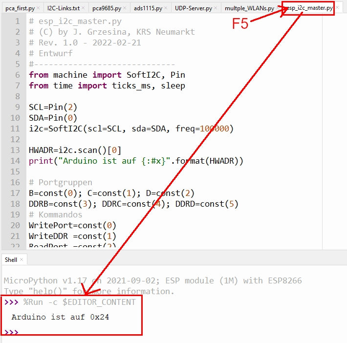
Image 11: Start MicroPython program
We have the RGB LED connected to pins D2, D3, and D4. They belong to the port PORTD and have the same numbers. In the DDR these pins have to be switched as output. Bit2, Bit3, and Bit4 (from right to left, starting at 0) are set to 1.
>>> writeDDR(D,0b00011100)
3
3 bits were sent over the bus. Whether they have arrived correctly and have been processed will be seen immediately after the next call.
>>> writePort(D,0b00011100)
3
And look - the LED emits white light, so all three channels must be switched on. Cross-check - the red LED is on PD3 - so give it a quick wiggle and wag ... lumos!
>>> writePort(D,0b00001000)
3
I just turned off the green (PD3) and blue (PD4) channels, red light remains.
Let's make a small light organ to finish this post.
Just type the following lines at the very end of the file esp_i2c_master.py or remove the comment characters from the download. After saving (Ctrl + S) start again with F5.
 writeDDR (D,0b00011100) # PD2,PD3,PD4 on output
 writePort(D,0)          # all output lines to 0
 while 1:                # continuous run
 for i in range(8):      # run from 0 to 7
     writePort(D,i<<2)   # the bits of i by 2 pos. to the left
     sleep(1)            # small pause
Have fun experimenting further! By the way, you can find the posts about MicroPython that have been published so far here.


