This article is also available as PDF file for download.
Welcome to another contribution to the series
MicroPython on the ESP32 and ESP8266
Probably you are asking yourself now, "Oh, then surely the wrong cover image slipped in here?" But no - the cover picture is already right here, it just has an incomplete caption, you better add "go ESP8266".

Figure 1: LDR, nRF24L01 and UNO
Indeed, the title of the current episode is:
AVR goes ESP with MicroPython - Part 1
A coexistence of controllers of the AVR family, like ATTinyXX or ATMega328, with their various other relatives on the one hand and the clan of the Espressif family ESP8266 and ESP32 on the other hand is very well possible. Of course, the intended wireless connection also works within the family. Of course, when it comes to wireless connections, a little help is needed with the AVRs and that is called nRF24L01+.

Figure 2: nRF24L01 with ESP8266-12F
One advantage of AVRs is for example their easy programming in assembler, which leads to small, lean programs. AVR controllers can also be completely without Arduino IDE easy to program. The serious disadvantage is the missing WLAN capability. Therefore this article is about how to dock an ATmega328 wirelessly to an ESP8266 or ESP32.
The widely used ATmega microcontrollers have one thing in common, the SPI bus. Widely used is the programming of an AVR controller via the Arduino IDE and the RS232 port of the AVRs. But then each of these chips is also equipped with an SPI interface. Via this interface the controller receives the programming with a bootloader, which enables it to react to a programming via RS232 in the first place. Of course this SPI interface can also be used for other purposes, for example for a connection to an ESP32 or ESP8266. In this respect an AVR controller is quite different from an ESP chip, which basically receives its data and programs via the USB/RS232 connection.
An ESP8266 or ESP32 has two such SPI interfaces. One to interact with the on-board EEPROM and a second one to connect external SPI devices. An AVR controller needs the SPI interface only during programming via this interface, after that it is free. In this project we make use of the SPI interface of both systems.
So you could simply use the SPI interface for communication between AVR and an ESP controller directly. However, this would require a cable connection. Maybe I will come back to this in a follow-up article.
Today I will present the first part of a project that uses this interface on both controllers, AVR and ESP8266, to establish a connection via another radio unit whose range is given by different sources between 250m and 1000m. We are talking about a module nRF24L10+, which also works on the frequency band of 2.4GHz, like our well-known WLAN. AVR and ESP8266 will therefore communicate wirelessly via radio.
This is not based on any of the usual transmission protocols like TCP/IP or UDP. So for the most part we have to take care of the integrity of the data ourselves, if necessary.
In today's post, we'll take a closer look at the nRF24L01+ from a MicroPython perspective. We will take a closer look at the MicroPython module with the class NRF24L01 and develop a program on the basis of which two ESP8266/32 can communicate with each other, bypassing the WLAN and the protocols TCP and UDP.
Basics
The nRF24L01+ - module, which is used here, is addressable via the SPI bus and has two additional control lines, CE and CSN. The IRQ connection is not used.

Figure 3: nRF24L01
The shape of the antenna on the board is reminiscent of the ESP8266-01. In fact, the nRF24L01 uses the same frequency band on 2.4GHz. Unfortunately, this can also lead to mutual interference, but more about that later.
The circuit for an ESP8266 is shown in the following figure. Four digital pins and the analog input are still available. The pin numbers on the board of the ESP8266 D1 mini are based on the Arduino IDE. The pin numbers for use under MicroPython have been added, highlighted in gray.

Figure 4: nRF24L01 on the ESP8266
Of course you can also use an ESP32. Its connections are then as follows. CE and CSN are connected to pins 5 and 4 on the ESP32 as well as on the ESP8266. In the program it looks like this for example.
- MISO = Pin(15)
- MOSI = Pin(13)
- SCK = Pin(14)
- CSN = Pin(4, mode=Pin.OUT, value=1)
- CE = Pin(5, mode=Pin.OUT, value=0)

Figure 5: nRF24L01 with adapter on ESP32 and loose LDR
The nRF24L01 board may only be operated with a voltage of max. 3.3V. although the logic lines are 5V compatible. There is a breadboard adapter with integrated 3.3V voltage regulator (AMS1117 3V3) for the board, but then it must be supplied with 5V (Figure 5).

Figure 6: nRF24L10 adapter
For this case an external 5V supply is drawn in the schematic with the ESP8266 (Figure 4), which is then also connected to the breadboard adapter of the nRF24L01, but it must be never directly with the Vcc pin of the nRF24L01!
The shown ESP8266 Node-MCU V3 is a special case among the ESP boards. On this board the 5V supply of the USB cable is not connected to the pin Vin but it is available on the other boards of the family. For the Adapter of the nRF24L01 an external voltage source is mandatory, for the other ESP8266 boards the supply of the nRF24L01 adapter can be done via pin Vcc through the USB port.
Without the breadboard adapter, the nRF24L01 can of course always be powered directly from the 3.3 V pin of the ESP8266/ESP32, as shown in Figure 4. Figure 5 shows the connection scheme with adapter.
I will come back to the operation and programming of the nRF24L01+ later. Let's first deal with the hardware used in the project. The circuit diagrams quickly show the parts needed for this project.
Hardware
|
1 |
|
|
1 |
|
|
2 |
|
|
2 |
|
|
1 |
LDR with 10kΩ trimpot or |
|
1 |
|
|
2 |
|
|
various |
Jumper cables |
|
2 |
suitable USB cables |
|
1 |
battery 4,5V or 5V wall adapter |
The wiring of the two modules with the AVR and the ESP8266 is certainly no problem. But let's have a closer look at the construction of the light sensor with the LDR. The two variants differ in the circuit and the used resistor.

Figure 7: Circuit of the LDR module
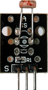
Figure 8: LDR module
At LDR module the photoresistor is connected to ground (GND), the fixed resistor to the positive supply voltage. Both resistors form a so-called voltage divider. When the LDR is exposed to light, its resistance value decreases, which causes the voltage at the signal output S to decrease. So the more the LDR is illuminated, the less output voltage we get. This also decreases the value of the AD converter on the ESP8266 or on the AVR that we want to use as a transducer. By the way, I describe here the use of a LDR as sensor, because the implementation is very simple. Of course any other sensor can be used, for example on the I2C bus. This article is mainly about the interaction between nRF24L01 and ESP8266.
The setup with LDR and trim potentiometer works exactly the other way around.

Figure 9: LDR in the film box lid

Figure 10: Brightness sensor

Figure 11: with trim potentiometer for brightness adjustment
The circuit is housed in a film can of translucent material, which scatters the incident light. The LDR is thus exposed more evenly from different directions. Because it is now connected against Vcc = 5V, as the illumination increases, the voltage at point S increases, more light, lower resistance, higher voltage, higher ADC value at the controller. Because the fixed resistor has been replaced by a trimmer, the output voltage range can be additionally adjusted to the range of the incoming light quantity. Besides the film can, the sawed-off plastic ball of an LED lamp is also suitable for covering. It distributes the light even more homogeneously.
The software
For flashing and programming the ESP32:
Thonny or
Putty as second terminal beside Thonny/µPyCraft
Used firmware for the ESP8266/ESP32:
Please choose a stable version
The MicroPython programs for the project:
nRF24simple.py Module for the ESP8266/ESP32
master+slave.py: Demo program for the ESP8266/32 TX+RX function of the nRF24L01
startnrf24.py: Test program for the ESP8266/32 TX+RX function of the nRF24L01
MicroPython - Language - Modules and Programs
For the installation of Thonny you find here a detailed manual. In it there is also a description of how the MicropythonFirmware (as of 26.01.2022) on the ESP chip. burned is burned.
MicroPython is an interpreter language. The main difference to the Arduino IDE, where you always and only flash whole programs, is that you only have to flash the MicroPython firmware once at the beginning to the ESP32, so that the controller understands MicroPython instructions. You can use Thonny, µPyCraft or esptool.py to do this. For Thonny, I have described the process here here.
Once the firmware is flashed, you can casually talk to your controller one-on-one, test individual commands, and immediately see the response without having to compile and transfer an entire program first. In fact, that's what bothers me about the Arduino IDE. You simply save an enormous amount of time if you can do simple tests of the syntax and the hardware up to trying out and refining functions and whole program parts via the command line in advance before you knit a program out of it. For this purpose I also like to create small test programs from time to time. As a kind of macro they summarize recurring commands. From such program fragments sometimes whole applications are developed.
Autostart
If you want the program to start autonomously when the controller is switched on, copy the program text into a newly created blank file. Save this file as boot.py in the workspace and upload it to the ESP chip. The program will start automatically at the next reset or power-on.
Test programs
Manually, programs are started from the current editor window in the Thonny IDE via the F5 key. This is quicker than clicking on the Start button, or via the menu Run. Only the modules used in the program must be in the flash of the ESP32.
In between times Arduino IDE again?
If you want to use the controller together with the Arduino IDE again later, simply flash the program in the usual way. However, the ESP32/ESP8266 will then have forgotten that it ever spoke MicroPython. Conversely, any Espressif chip that contains a compiled program from the Arduino IDE or the AT firmware or LUA or ... can easily be flashed with the MicroPython firmware. The process is always like here described.
The programming of the nRF24L01(+)
Like all peripheral devices, with more or less complex inner workings, the nRF24L01 also has various registers, i.e. internal memory locations, via which configuration and communication take place. In addition, there are 11 command codes that can be used to control the function of the device. The MicroPython module nrf24simple.py closely follows the register names and instruction names from the data sheet for the nRF24L01 data sheet. The methods of the class NFR24L01 from this module are part of the Arduino library for the nRF24L01+ but are mostly shorter and clearer.
The SPI bus
But let's start with the SPI bus. While the I2C bus has only two lines, the SPI bus has four: SCK, MISO, MOSI and -CSN. With the nRF24L01+ a fifth line is added. The radio module is activated via CE. The connection is only drawn for completeness and has nothing to do with the SPI interface.

Figure 12: SPI bus lines
On SCK (Serial Clock), the controller as master sets the clock rate at which bit by bit is shifted over the data lines.
On MOSI (Master Out Slave In) data are pushed from the master to the slave (nRF24L01).
On the MISO-line (Master In Slave Out) the bits come simultaneously from the slave to the master.
The Chip Enable line CE, I already mentioned, has nothing to do with the operation on the SPI bus, but must only be at HIGH potential during the whole transmitting or receiving process of the nRF24L01. So it switches on the "radio device". When sending, first the send buffer is filled via SPI, then CE goes to 1, we wait shortly and then switch CE back to 0. The method transmit() works exactly the same way. Listening at the radio also starts with CE=1 and also ends with CE=0. You can do this with the methods startListening(), stopListening() method. The fetching of the data is done by the method getData(), which is called whenever bytesAvailable() True if characters have arrived and are ready in the receive buffer.
-CSN activates the SPI interface if a LOW signal is present there. This corresponds to the usual interface protocol. -CSN goes to LOW, characters move simultaneously via MOSI and MISO immediately afterwards -CSN goes HIGH again.
Compared to the I2C bus it is remarkable that the data exchange, as already indicated, takes place simultaneously with SPI. So a bit sent from the master to MOSI is always sent from the slave to MISO. In the case of the nRF24L01 the transfer of a byte starts with the MSBit, the Most Significant Bit, i.e. the bit with the highest significance. However, when several bytes are transferred via the SPI interface, the LSByte, i.e. the byte with the lowest significance, is always transferred first, for example the pipe address.
The sending of a hardware address on the part of the master as with the I2C bus is not necessary, because the chip selection is done via the -CSN line. At each negative edge on this line, i.e. each HIGH-LOW change, the nRF24L01 always automatically sends the contents of its status register on the MISO line with the first 8 clocks, while the controller simultaneously clocks a command byte on the MOSI line. The level on the data lines MISO and MOSI is taken over respectively with the rising edge on the clock line SCK. The black arrows in Figure 13 indicate the direction of the data flow, the time axis always runs from left to right. The clock frequency is 1 MHz.

Figure 13: SPI data transfer

Figure 14: The flushRX command on the DSO
From the DSO plot we read out that track 1 must be the clock line with 4MHz and just the command flushRX (clear the receive buffer) on channel 2 moves over the line MOSI. The command byte for this is 0xE2 = 0b11100010. The pulse at valence 2 clearly shows that the level change on MOSI occurs with the falling clock edge and the sampling occurs with the rising edge on SCK. In addition, the transmission starts with a 1, the MSB.
Some nRF24L01 commands and registers
Commands to the nRF24L01 are encoded by the 11 command bytes, nine of which have been defined as separate methods in the NRF24L01 class. They in turn use other methods of the class to operate the SPI bus for writing and reading. The basis for converting the commands into MicroPython code is the Data sheet of the module. There we find on page 39 the list of the command codes with explanation, on the pages 45ff follows analogously the representation of the registers.
The instantiation of the required SPI object is done in the main program, matching the used controller, ESP8266 or ESP32. The bus can therefore also be used in parallel for other SPI devices with their own CS pin. The variable sys.platform provides the type of the controller.
When calling the constructor of the class NRF24L01 the SPI object is passed as the first parameter. This is followed by the references to the pin objects for the -CSN- and the CE-line. Optionally the channel number (default: channel=50) and the number of bytes for the payload (default: payloadSize=8) can be specified.
The constructor automatically sets the number of address bytes for pipe 0 and 1 to 5, the transmit strength to minimum (-18dBm) and the bitrate for the radio to 250kB/s. The latter gives us the highest receive rate. The latter gives us the highest receive sensitivity. An instance variable buf is declared as a byte array of length 1 and takes over the role of the receive buffer for the read-write commands of the SPI object when sending a command byte.
We now take a closer look at some of the methods as representatives. The rest uses these or similar methods.
     def readReg(self,reg):
         self.csn(0)
         self.spi.readinto(self.buf,reg | READ_REG_CMD)
         self.spi.readinto(self.buf)
         self.csn(1)
         return self.buf[0]
readReg() reads the content of one of the 8-bit registers of the nRF24L01. Here the flow of the data traffic from figure 13 is mirrored. -CSN is set LOW for the data transfer via the SPI bus. The register number is ored with the read command for register.
Example:
Register to be read: 0x0B
Read command: 0x20
Command byte: 0x20 | 0x0B = 0x2B
The first SPI command readinto() reads the status byte from MISO and simultaneously outputs the byte 0x2B on MOSI. Because the -CSN line was put LOW shortly before, the nRF24L01 sends the content of the status register, which is discarded here. After all, we are only interested in the content of the byte contained in reg and this is read by the next readinto() command reads in. -Set -CSN to HIGH level and read the contents of the buffer. buf at position 0 (i.e. the one byte) as a number - done.
     def writeReg(self,reg,val):
         self.csn(0) # Initiate command
         self.spi.readinto(self.buf,reg | WRIT_REG_CMD)
         state=self.buf[0]
         self.spi.readinto(self.buf, val)
         self.csn(1) # SPI transfer finished
         return state
writeReg() starts similarly, but now we store the state in state between. It is interesting that we start with another readinto() we can read the contents of the targeted register in nRF24L01 there. write. It is because reading and writing are done simultaneously via the SPI bus. This means that by the read command the content of val on MOSI moves to the nRF24L01. What now arrives via MISO disappears in nirvana. Instead we return the cached status.
     def writeBuffer2Reg(self,reg,buffer):
         # writes the content of buffer to register reg
         self.csn(0)
         self.spi.readinto(self.buf, WRIT_REG_CMD | reg)
         self.spi.write(buffer)
         self.csn(1)
         return self.buf[0]
Only if more than one byte is to be written, we use the spi.write() command. It sends each byte in buffer to the nRF24L01. But this also means that the buffer must not be longer than the payload it transports.
These three methods are used by almost all other methods for data transfer. setChannel() limits the passed value of the channel number to the valid range and transfers the result to register RF-CH (=0x05).
     def setChannel(self,channel):
         # set channel number 0..125
         self.writeReg(RF_CH, max(0,min(channel, 125)))
There are three methods we use that do not send any byte other than the command byte. These themselves also use the readinto() method, such as flushTX().
     def flushTX(self):
         # Empty send buffer, command parameterless
         self.csn(0)
         self.spi.readinto(self.buf, FLUSH_TX)
         self.csn(1)
The nRF24L01 is configured by querying and setting register contents.
     def setTXConfig(self,baud,power):
         # sets power and speed
         val=(self.readReg(RF_SETUP)&0b11010001)|baud|power
         self.writeReg(RF_SETUP,val)
Read RF_SETUP register, reset the relevant bits by undo and set the new values by undo and then write back to the register. Here the baud rate and the transmission strength for the radio are set.
Registers also play a role for the data traffic itself.
     def getData(self):
         self.csn(0)
         self.spi.readinto(self.buf, R_RX_PAYLOAD)
         buffer = self.spi.read(self.payloadSize)
         self.csn(1)
         self.writeReg(STATUS, RX_DR)
         return buffer
When data arrives by radio, we retrieve it, getData(). To do this, we send the command R_RX_PAYLOAD = read the received data. Then we fetch as many bytes as are contained in the instance variable PayloadSize was set. -CSN goes back to 1 and after clearing the receive flag. RX_DR in the register STATUS we return the buffer contents.
A remarkable method, which has not directly something to do with the nRF24L01 registers, is TimeOut(). It defines with compare() a so-called closure.
     def TimeOut(self,t):
         start=ticks_ms()
         def compare():
             return int(ticks_ms()-start) >= t
         return compare
An t we pass a time duration in milliseconds. Within TimeOut() we define the function compare(), to which TimeOut() returns a reference. compare() compares the difference between the current time and the start time with the passed time span in t and returns True back when t ms have expired. With the call of TimeOut() we set t to 10000, for example.
>>> timer=TimeOut(10000)
timer() now represents a function itself, because we have given the variable the reference to compare() to the variable. We can now use timer() in the Thonny terminal and get False as response until 10 seconds have passed. timer() is a closure whose habit is to remember the contents of local variables on the next call, even if the function was exited in between.
With TimeOut() you can set up (almost) any number of timers with (almost) any expiration times. Another special feature is that these timers do not block the program flow as for example sleep() or sleep_ms().
All commands needed for our project have been implemented in corresponding methods. You can find these and a few more in the file nrf24simple.pywhich we include as a module in our program. So that we can test the methods of this module by hand on the command line of Thonny, I have included the definition part of the program discussed below master+slave.py into the test program startnrf24.py is copied. We can start this program from the editor window with F5 to start it. In the terminal all methods of the class NRF24L01 are now manually checkable in the test.
Master and slave
Essential points of the data traffic from and to the nRF24L01 via SPI and the radio data transmission are treated, then we go now into the final spurt. To test the whole system we need a transmitter and a receiver. To avoid having to maintain two programs, I packed the two units into one program. One line decides about transmitter (master = True; slave=False) or receiver (master=False; slave=True). We find this in the listing line 8 and 9 respectively, depending on which of the two is uncommented. A few more classes and methods are to be imported besides NRF24L01 for our intention.
 # master+slave.py
 import sys, os
 from time import sleep_ms,ticks_ms
 from machine import Pin, SPI
 from nrf24simple import NRF24L01
 # -------------------------------------------------------
 #master=False; slave=True
 master=True; slave=False
 # -------------------------------------------------------
 led=Pin(2,Pin.OUT,value=1)
 def blink(led,pulse,wait,inverted=False,repeat=1):
     for i in range(repeat):
         if inverted:
             led.off()
             sleep_ms(pulse)
             led.on()
             sleep_ms(wait)
         else:
             led.on()
             sleep_ms(pulse)
             led.off()
             sleep_ms(wait)
We use the onBoard-LED, if available, for the feedback of program states, because we don't have a terminal available for the outdoor test. The function blink() helps us as usual. It can generate blink pulses individually or as a sequence with variable pause duration and takes into account by the optional parameter inverted both LEDs connected to ground (True), as well as those that are activated by the HIGH level at the output pin (False). We use this also immediately for the first error message, if master and slave both accidentally on True were set.
 if master and slave:
     blink(led,500,100,inverted=True,repeat=5)
     raise OSError ("EITHER slave OR master!")
chip=sys.platform
taste=Pin(0,Pin.IN,Pin.PULL_UP)
if chip == 'esp8266':
# pin translator for ESP8266 boards
# LUA pins D0 D1 D2 D3 D4 D5 D6 D7 D8
# ESP8266 pins 16 5 4 0 2 14 12 13 15
# SC SD
bus = 1
MISOp = Pin(12)
MOSIp = Pin(13)
SCKp = Pin(14)
spi=SPI(1,baud rate=4000000) #ESP8266
# # alternatively virtual with bitbanging
# spi=SPI(-1,baudrate=4000000,sck=SCK,mosi=MOSI,\
# miso=MISO,polarity=0,phase=0) #ESP8266
if slave:
adc=ADC(0)
elif chip == 'esp32':
bus = 1
MISOp= Pin(15)
MOSIp= Pin(13)
SCKp = Pin(14)
spi=SPI(1,baud rate=4000000,sck=Pin(14),mosi=Pin(13),\
miso=Pin(15),polarity=0,phase=0) # ESP32
if slave:
adc=ADC(Pin(39)) # Pin SP
adc.atten(ADC.ATTN_11DB)
adc.width(ADC.WIDTH_12BIT)
else:
blink(led,800,100,inverted=True,repeat=5)
raise OSError ("Unknown Port")
at(MISOp,MOSIp,SCKp))
print("Hardware bus {}: Pins fixed"..format(bus))
print("MISO {}, MOSI {}, SCK {}\n".format(MISOp,MOSIp,SCKp))
We have the module sys because the string sys.platform tells us the type of the port. Depending on this we can react individually to the peculiarities of the SPI bus and to the setup of the analog input. The two print-commands inform about what was finally set.
 CSN = Pin(4, mode=Pin.OUT, value=1)
 CE =  Pin(5, mode=Pin.OUT, value=0)
 nrf = NRF24L01(spi, CSN, CE, payloadSize=8)
 channel=50
 pipeAdr=[0x5A5A5A54,0x5A5A5A52]
CSN and CE are on the same GPIO pins for ESP32 and ESP8266. nrf is the instance of the class NRF24L01which is defined with the default 5 bytes address width and a payload length of 8 bytes. The variable for the channel number is set to 50. Each radio channel can receive messages from slave units via up to 6 so-called pipes. For this, each pipe needs a unique number, the pipe address. The address for the receive pipe 0 (RX) is also used for the transmit pipe (TX). Like pipe 1, it is defined by the agreed 5 bytes. It is sufficient if the addresses of the receive pipes differ by one byte. This is usually the LSByte. The two to four higher bytes represent quasi the group address of the channel. These bytes are also used transparently for addressing the pipes 2 to 5 for which only one LSByte can be set as address in the nRF24L01. The remaining address bytes are taken from those of pipe 1. The transmission of the address to the nRF24L01 via SPI starts with the LSByte. This fact is supported by methods openTXPipe() and openRXPipe() are automatically taken into account.
By the way, the transmit frequency of the channel is obtained by adding the channel number with the unit MHz to the base of the frequency band 2400 MHz. Channel 50 thus transmits and receives on 2450 MHz or 2.450 GHz.
The nRF24L01 can do two jobs:
- a) Connect two stations bidirectionally in half-duplex.
Both stations, master and slave, can transmit alternately on the same frequency (channel). The slave is first listener (listener, receiver) and waits for the receipt of a message from the master (transmitter, sender). Then the slave does its job from the request and sends back the result.
- b) A receiver can have up to six logical connections. to transmitters, called pipes, on one channel. Half-duplex is possible, but costly to program. The six input pipes of the receiver are set to the addresses of the six transmitter units.
The master
The following program uses version a). First, let's take a closer look at the program for the master.
 if master:
     tryMax = 5
     successful = 0
     error  = 0
     passage = 0
     nrf.setChannel(channel)
     print("MASTER mode: Sending on channel ",channel)
     nrf.openTXPipe(pipeAdr[1])
     nrf.openRXPipe(1, pipeAdr[0])
     print("MASTER mode, send {} packets"..format(tryMax))
     nrf.info()
With trymax=5 we specify the number of connection attempts. We let the passes, hits and misses, be counted. The given channel is set, then we open the send and receive pipes by assigning the unique addresses to the connections. nrf.info() provides us with quite a bit of information about the configuration of the nRF24L01. The following points must be taken into account when assigning addresses.
- Each unit has a TX pipe whose address is also assigned to RX pipe 0 at the same time. This makes the method openTXPipe().
- The method openRXPipe(nr,adr) assigns the address adr to the RX pipe nr.
- From the RX address adr only the LSByte is picked if nr >= 2.
- The MSBytes of the pipes 2 to 5 are taken over from pipe 1 (gray in fig. 15)
- The address of TX and therefore RX pipe 0 may differ from the other addresses in every byte.
- The addresses for a pipe must match on the send and receive side.
- Similar to the cable connections at a RS232 connection the assignments must be crossed.
- After the cold start of the nRF24L01, addresses are already set up according to these specifications.
After starting startnrf24.py in the editor window with F5:
>>> nrf.info()
Issue:
 …
 Receive Address, pipe 0: b'\xe7\xe7\xe7\xe7\xe7'
 Transmit Address: b'\xe7\xe7\xe7\xe7\xe7'
 Receive Address, pipe 1: b'\xc2\xc2\xc2\xc2\xc2'
 Receive Address, pipe 2: b'\xc3'
 Receive Address, pipe 3: b'\xc4'
 Receive Address, pipe 4: b'\xc5'
 Receive Address, pipe 5: b'\xc6'

Figure 15: Master and slave - connection assignment as for RS232
Point f.) from the above list makes it clear that half-duplex operation with several slaves is associated with increased effort. In order to be able to radio six slaves, the TX address of the master would have to be exchanged with each change of connection.

Figure 16: Multi-transmitter mode
     while passage < tryMax:
         nrf.stopListening()
         text="send:{}".format(passage)
         print("\nsending:", text)
         try:
             nrf.sendData(text.encode())
         except OSError:
             pass
The while loop counts the passes and can easily be replaced by while 1: in the production system. We stop the eavesdropping mode by stopListening(). This switches off the radio module of the nRF24L01. The text to be sent is compiled and sent coded as a byte object. Occurred errors are indicated by try - except are intercepted. The method sendData() switches the send module on and off independently at a given time.
         nrf.startListening()
         timedOut=nrf.TimeOut(50)
         timeState=timedOut()
         while not nrf.bytesAvailable()and not timeState:
             timeState=timedOut()
We now wait for the answer from the slave and for this we switch the radio back on and to listening station. We make the timer timedOut() to 50ms and wait for received bytes. timeState is set with True and is set to the state of the timer with each loop pass.
         if timeState:
             print("Timeout!", passage)
             error += 1
             blink(led,50,200,inverted=True)
         else:
             response=nrf.getData()
             print("Passage:",passage)
             response=response.decode()
             print("Response:",response.strip("\x00\n\r"))
             successful += 1
If no characters have been received within 50ms timeState True. We increment the error counter and output a timeout message.
Otherwise we fetch the data, decode to the string from which we remove the non-printing characters (\x00, linefeed and carriage return) and output the text. Finally, we add one more for the success counter.
         blink(led,50,950,inverted=True)
         pass +=1
     print("Out of {} passes, {} were successful.".\
           format(tryMax,successful))
A "blink" after each pass pauses together for one second until the next query. Then final summary, master part done.
The slave
The slave starts almost the same as the master, but we have to note the reverse assignment of addresses. The TX pipe gets address 1 and the RX pipe 1 gets address 0.
 if slave:
     nrf.setChannel(channel)
     nrf.openTXPipe(pipeAdr[1])
     nrf.openRXPipe(1, pipeAdr[0])
     nrf.info()
     nrf.startListening()
     print("SLAVE mode: Listening on channel ",channel)
Then it already goes into the job loop.
     while True:
         buffer = b''
         if nrf.bytesAvailable():
             #print(".",end='')
             while nrf.bytesAvailable():
                 recv=nrf.getData()
                 print(recv)
                 buffer = buffer+recv
                 sleep_ms(15)
             msg=buffer.decode()
             print("got:",msg)
             pos=msg.find(":")
             value=str(adc.read())
             response=value.encode()
We delete the bytes object bufferin which the received characters are collected as long as some arrive. We decode the byte object to a string and look for a ":". We could now check if the characters up to the colon correspond to a command and what number follows. Instead I get the LDR value from the ADC, convert it to a string and encode it as a byte object.
             nrf.stopListening()
             try:
                 nrf.sendData(reply)
                 blink(led,50,1950,inverted=True)
             except OSError:
                 pass
             print("sent: {}".format(reply))
             nrf.startListening()
         if key.value()==0:
             sys.exit()
With stopListening() we switch to the send mode. We send our response and then start the eavesdropping attack again.
With the flash button on the ESP8266 board we can abort the program at this point to get back to the edit mode.
With the download of the file master+slave.py you will get the complete program text.
The test
For the test we need a station according to the pattern of figure 4 as master and a circuit according to figure 5 as slave. You can also use an ESP8266 as a slave, but then you have to use for the slave the Remove the master part of the programotherwise you will get memory problems.
To be able to control and monitor both units, we need a second terminal. For this we use Putty. It is best to download a executable version for your system and save it in a directory of your choice.
We now plug the master unit into the PC and will set it up for autonomous startup.
 #master=False; slave=True
 master=True; slave=False
The program is declared as master. On the ESP8266 we load the module nrf24simple.py and then call up the configuration, at the bottom right of the Thonny window.

Figure 17: Call up configuration

Figure 18: Options for the master unit
The number of the COM interface, here COM6we remember it for later, OK. We call via the key F5 we call the program master+slave.py in the editor window. If it runs without errors, we can ignore the timeout messages for now, we mark the whole text with Ctrl+A and copy it to the clipboard. Now we open the file boot.py from the ESP8266 by double-clicking it in an editor window.

Figure 19: Open boot file from ESP8266
We select all the text there again by Ctrl+A and paste our program text from the clipboard. Our text replaces the selected one. With Ctrl+S we save the boot.py back to the board.
Next, we plug the slave setup into the PC and change the configuration of Thonny.

Figure 20: Slave configuration
With this we have the connection COM6 under Thonny and can now use it in Putty. After Putty has started, we set the parameters in the same way as in Figure 21 and save the profile. Save. With Open a terminal is opened.

Figure 21: Run Putty

Figure 22: Putty sample configuration
All messages that were previously displayed in Thonny in the terminal area now appear in Putty after the master has been restarted by pressing the RST key. After this, the command line prompt of MicroPython is displayed.
We switch back to the Thonny environment and set the ESP32 as the slave.
 master=False; slave=True
 #master=True; slave=False
After saving we start with F5 the program master+slave.py in the editor window and reset the master board. If the output in the terminal windows now looks similar to figures 23 and 24, then you have managed to open up a new communication path for the two ESPs.

Figure 23: Output in the slave terminal

Figure 24: Output at the master terminal
Of course, it is certainly interesting that ESPs can sometimes talk to each other undetected by WLAN traffic. But much more crucial is the case that AVRs can dock to a relay station via radio, which can then relay their messages to the WLAN. That's exactly what we'll look at in the next episode. More from AZ-Delivery published blog posts about MicroPython, AVR and Raspberry Pi can be found at here, or in the Blog section.


6 comments
Anstela
Hallo @Khalil
vielen Dank für den Hinweis. Die Links sind jetzt aktualisiert und sollten funktionieren.
Grüße,
Anstela
AZ-Delivery Blog
Khalil
Hallo ,
die Linke funktionieren nicht !
The MicroPython programs for the project:
nRF24simple.py Module for the ESP8266/ESP32
master+slave.py: Demo program for the ESP8266/32 TX+RX function of the nRF24L01
startnrf24.py: Test program for the ESP8266/32 TX+RX function of the nRF24L01
Grüße .
Khalil
Jürgen
@ Werner:
Bitte vielmals um Entschuldigung, ich hatte die Datei beim Hochladen übersehen. Jetzt funktioniert der Link.
Grüße
Jürgen
Willem
Hallo,
der Link startnrf24.py funktioniert immer noch nicht,
Willem
Andreas Wolter
@Werner: vielen Dank für den Hinweis. Wir werden das korrigieren.
Grüße,
Andreas Wolter
AZ-Delivery Blog
Werner
Da ist etwas schief gelaufen,
der Link http://www.grzesina.de/az/arduino_goes_esp/startnrf24.py funktioniert nicht.
Werner