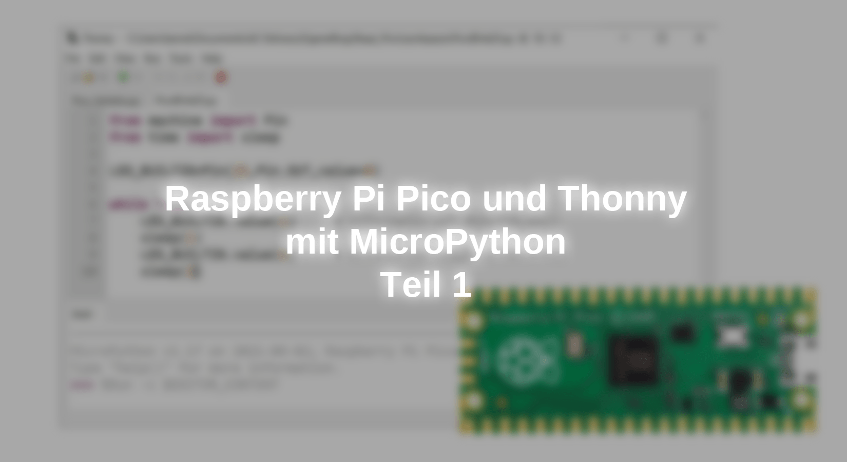
Why simple, if it is also difficult? That's what I thought when I tried to find a solution with the help of the official documentation. "Getting started with Raspberry Pi Pico". of the Raspberry Pi Foundation to get the Pico running on my Raspberry Pi 400. I refrain from further comments but rather describe how easy it is to program the Raspberry Pi Pico under Thonny with MicroPython. For this, I use either my PC or my Raspberry Pi 400. Please also note our Pico Quickstart Guide.
Installation
The Python editor Thonny is quickly installed on the PC, on the Raspberry Pi it is part of the basic equipment of the operating system Raspberry Pi OS (formerly Raspbian). The settings for the respective microcontroller and associated MicroPython are made after the start.

At thonny.org select the operating system, download, and installation will take less than five minutes.

Under Tools\Options, you can set the language on the first tab (General).

After changing the language setting, Thonny must be closed and restarted.
We then proceed to the settings for the Raspberry Pi Pico. Here, we experience the only real stumbling block when programming the Pico with MicroPython.

Using the Run menu\Select Interpreter ... we get to the second tab of the options. After selecting the Raspberry Pi Pico, we press and hold the single BOOTSEL button on the Pico and then plug the Pico into the USB socket. In boot mode, the Pico will temporarily log in to the Windows 10 PC as a new drive. (Windows 7/8 users please use the blog post by Andreas Wolter read).


After installing the MicroPython firmware, the drive disappears again and we receive the Python-typical prompt >>> in the command line (lower part of Thonny, often also called shell or REPL= read-eval-print loop).

Now we can either write a first program in the upper part, the editor, or behind the prompt, the usual print("Hello World") and press Enter.
Trouble Shooting: If you get an error message instead of the above picture, it may be because the COM port of the pico was not detected automatically. Then please select the correct port in the pull-down menu on the Options\Interpreter page.

If this does not work, please repeat the installation: unplug the USB connector, press BOOTSEL, plug in the USB connector, release BOOTSEL, and so on.
Application programs
If you already have experience with Python, e.g. with the Raspberry Pi, you will find only a few peculiarities with MicroPython on the Pico. No difference e.g. when writing "Hello World" five times with a display of the count variables:

When saving, you are asked if the program should be saved on the computer or on the pico. Recommendation: Save everything on the computer. Later we will see what is additionally saved on the pico.

The program can only be executed after saving, whereby Thonny automatically saves further changes after pressing the start icon.
Already with our second program, we want to move on to "Physical Computing", i.e. use the many interfaces that our microcontroller provides. For this purpose, we import two program modules (Arduino users would say library or lib) at the beginning of the program. The module time is an old acquaintance for Raspians, the module machine is only known by those who have tried MicroPython on the ESP32. Here now the "Blink variant" in MicroPython:

From the module machine, the class Pin is imported, from time-only sleep. Those who import the classes in such a way can call them later without the module name. Who imports the whole module (e.g. import time), must prepend the module name to all statements (i.e. time.sleep(1)).
To the module, time calls the documentation next to sleep() also sleep_ms (milliseconds) and sleep_us (microseconds).
import time
time.sleep(1) # sleep for 1 second
time.sleep_ms(500) # sleep for 500 milliseconds
time.sleep_us(10) # sleep for 10 microseconds
start = time.ticks_ms() # get millisecond counter
delta = time.ticks_diff(time.ticks_ms(), start) # compute time difference
In the program the object LED_BUILTIN is instantiated at pin(25) as output with value 0 (switched off). In the endless loop, the built-in LED is then switched on and off every second.
In the third program, we also want to use the class Pin from the module machine. A traffic light cycle is to run when a key is pressed. The only new thing is the instantiation of the button as an input with a pull-up resistor. The button at pin 5 is switched to ground.
button = Pin(5, Pin.IN, Pin.PULL_UP)
To find the inputs and outputs I used, here is the official first Pinout diagram:

 from machine import Pin
 from time import sleep

 greenLED = Pin(4,Pin.OUT,value=0)     # green
 yellowLED = Pin(3,Pin.OUT,value=0)    # yellow
 redLED = Pin(2,Pin.OUT,value=0)       # red
 LED_BUILTIN = Pin(25,Pin.OUT,value=0)
 key = Pin(5,Pin.IN,Pin.PULL_UP)

 def trafficLight():
     greenLED.value(1)
     sleep(2)
     greenLED.value(0)
     yellowLED.value(1)
     sleep(2)
     yellowLED.value(0)
     redLED.value(1)
     sleep(5)
     yellowLED.value(1)
     sleep(2)
     yellowLED.value(0)
     redLED.value(0)
     greenLED.value(1)
     sleep(5)
     greenLED.value(0)
     return None

 while True:
     if key.value() == 0:
         print("button is pressed")
         trafficLight()
So much for a first look at the digital inputs and outputs. Now we turn to the analog inputs (ADC = Analog Digital Converter). Useful are
- ADC0 at GP26
- ADC1 at GP27
- ADC2 to GP28
If no reference voltage is connected to the physical pins 35 and 33, the readout values refer to 3.3V. In fact, it is only one ADC, to which a total of five inputs are connected by a "mux" (multiplexer). I did not find the fourth ADC (ADC(3) at GP29), at ADC(4) is the internal temperature sensor. More about this is in the Blog of Jörn Weise from 13.Nov.2021.
I connect my self-made game controller with the 10kOhm rotary potentiometer to phys. Pin 36 (3.3V), GND, and the ADC inputs. The following small program, which I modified slightly, is from the RP2 chapter of the MicroPython documentation.

On the Pico, MicroPython only knows the method read_u16, i.e. a 16-bit value between 0 and 65535. After trying a simple read() command unsuccessfully (i.e. with an error message), I divided the respective value by 64 to get the known 10-bit resolution from 0 to 1023. Everything else pretends an accuracy that is not given, as you can see from the number jumps with unchanged settings.
Instead of the instantiation made here in line 13 with the GPIO pin number adc=ADC(Pin26)) you can also use the index of the list ADC[0:4]:
- ADC(0) = Pin(26)
- ADC(1) = Pin(27)
- ADC(3) = Pin(28)
- ADC(3) = GP29 not found
- ADC(4) = temperature sensor

At the end of the first part, the well-known alternative to analog outputs: is pulse width modulation (PWM), which can be used to dim LEDs or throttle motors.

From the module machine, the classes Pin and PWM are imported, the object pwm0 is instantiated (the built-in LED is connected to pin 25) and the PWM frequency is set.
In an endless loop, the duty cycle of the PWM is regulated down to 0 (zero). After one second the process starts again.
The try: - except - construction causes the endless loop can be terminated with Ctrl-C without an error message.
Outlook
In the second part, we will get to know the known interfaces UART, OneWire, I2C, and SPI as well as the evaluation of sensors and output at the LCD.
