Today the new sensor came DHT20 by post. As always, my curiosity could not be broken and he had to be tried out immediately. Since the delivery was announced, I already had that Data sheet from the Internet Downloaded and read carefully. Because at first I did not want to believe that this sensor, externally identical to the DHT11 and DHT22, had an I2C interface. While the DHT11 are blue and the DHT22 white, the DHT20 comes with a black housing on a small breakout board that offers both more mechanical stability and easily readable lettering. In fact: the four pins are labeled with +, -, SCL and SDA. And thus, deviating from the actual PIN assignment of the actual sensor, in the usual order.
According to the data sheet, the supply voltage has a range of 2.2 to 5.5 volts, i.e. both for Raspberry Pi and ESPS and AVR microcontrollers.


Pin assignment of the breakout board
Next I join the DHT20 to one Microcontroller ATMEGA 328 and check the i2C address with the sketch i2c scanner. As described in the data sheet, the address is 0x38. We will see that later when I switch the Logic Analyzer parallel to the I2C bus.
Program code

To my great delight, there are already two program libraries. I test both and start with that of January 2022, which, according to the developer Rob Tillaart, is still in need of improvement, but is usable for our purposes and takes the complicated conversion of the sent bytes into the values of the relative humidity and temperature.

And as so often, the installation of the library also saves examples that can be found under/file/examples/DHT20.

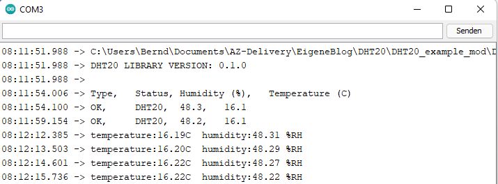
I try out the top example, only modify the sketch with regard to the time distances between the measurements and do without the output of a time stamp:
//
// File: dht20.ino
// Author: Rob Tillaart
// Purpose: Demo for DHT20 I2C Humidity & Temperature Sensor
//
DHT20 Dht;
void set up()
{
Dht.Begin();
Wire.setclock(400000);
Serial.Begin(115200);
Serial.print(__File__);
Serial.print("DHT20 Library version:");
Serial.print(Dht20_lib_version);
Serial.print();
delay(2000);
Serial.print("Type, \ tstatus, \ thumidity (%), \ ttemperature (c)");
}
void loop()
{
IF (Millis() - Dht.load() >= 1000)
{
// Read data
uint32_t begin = micros();
intimately status = Dht.read();
uint32_t stop = micros();
switch (status)
{
case Dht20_ok:
Serial.print("Ok, \ t");
break;
case Dht20_error_checksum:
Serial.print("Checks of error, \ t");
break;
case Dht20_error_connect:
Serial.print("Connect error, \ t");
break;
case Dht20_missing_bytes:
Serial.print("Missing bytes, \ t");
break;
default:
Serial.print("Unknown error, \ t");
break;
}
// Display data, sensor has only one decimal.
Serial.print("DHT20, \ t");
Serial.print(Dht.gefhumidity(), 1);
Serial.print(", \ t");
Serial.print(Dht.getting temperature(), 1);
Serial.print("\ t");
// serial.print (stop - start);
// serial.print ("\ n");
delay(5000);
}
}
// - End of file -
As I said, the actual performance is in the program libraries Dht20.cpp and Dht20.h. Here the library for the I2C-Bus Wire.H is included, the initialization bytes sent to the DHT20 and the data reception and the conversions for the functions DHT.GETHUMITITITY () and DHT.GET temperature () fixed.
Even if I find things like the I2C address and the names of the registers in the libraries, I look at the whole thing again with the Logic Analyzer, which I in February in a two-part blog (Part 1, Part 2). The entire measurement process takes place in two sequences from several bytes. First, the requirement is made by the microcontroller.

As described in the data sheet, four bytes are sent: "Write to address 0x38", "Invitation to measure 0xac" with the parameters 0x33 and 0x00.
Here is the picture from the data sheet:

Then there is a request to read the measured data. As a reminder: The I2C address consists of 7 bit, here 0x38 = 0B0111000. If the eighth bit 0 is, the sensor should “listen” as in the picture above, if the eighth picture 1 is, the sensor should send data as in the following picture:

The following six bytes contain the data for air humidity and temperature, the last a check sum (CRC Check Data). Here is the picture from the data sheet:

Now I would like to address the tension used again: The data sheet had mentioned the operating voltage between 2.2 V and 5.5 V. However, the following table limits the use in such a way that the logic voltage should only deviate minimally from the operating voltage:

I can not confirm. In my experiments on the microcontroller with ATMEGA328, I saw no significant deviations in the measured values. In the following picture, after four to five measurements, I had replaced the VCC between 3.3V and 5V.

I was unable to compare my idea of comparing the measured values of DHT11, DHT22 and DHT20 in a sketch because of the predominantly the same nomenclature in the libraries.
Instead, I operated a second micro controller with the DHT22 in parallel and compared the values, on the left in the picture of the DHT22, right of the DHT20:

There are small deviations within tolerance. Unfortunately, I cannot determine which sensor is more precise.
Finally I tried the second DF Robot program library. The agreement of the measured and then calculated values is not particularly surprising. In the upper half the results with the library of Rob Tillaart, in the lower half with that of Dfrobot.
Here, too, I look at the signals with the Logic Analyzer. The only difference: the data is read out twice per cycle (each for temperature and humidity) and only six data bytes are read. Obviously, the check of the check sum is dispensed with.


Both program libraries seem suitable for the purpose, both can still be improved. I read a program line for ESP8266 and ESP32 in the Rob Tillaart library, which of Dfrobot is not. Therefore, I recommend ESP users the first-mentioned library.
Finally, a comparison of the parameters from the data sheets:
|
sensor |
DHT 11 |
DHT 20 |
DHT 22 AM2302 |
|
Temperature range |
0 to 50 ° C |
-40 to 80 ° C |
-40 to 80 ° C |
|
Accuracy temperature |
+/- 2 ° C |
0.5℃ |
+/- 0.5 ° C |
|
Area rel. Air humidity RH |
20 to 90% RH |
0 to 100% RH |
0 to 100% RH |
|
Accuracy RH |
+/- 5% RH |
+/- 3% |
+/- 2% RH |
In the past, we have shown many application examples for temperature and humidity sensors. With the DHT20 there is now another well-suited sensor with the proven I2C interface. In the end, the price should influence the purchase decision.


11 comments
Grille
Hallo
Da ist eine Inkontinenz äää Inkonsistenz in der Beschreibung:
Zitat Text:
<<Tatsächlich: die vier Pins sind mit +, -, SCL und SDA beschriftet. Und damit, abweichend von der tatsächlichen Pin-Belegung des eigentlichen Sensors, in der üblichen Reihenfolge.>>
und zwei Zeilen darunter ist eine <>, die von der Reihenfolge +, SDA, GND, SCL schreibt, darunter wieder ein Bild vom BrakoOutBoard (“BOB”) das der Pinreihenfolge m Text entspricht. Das ist verwirrend.
Ich vermute, dass in der Tabelle die Belegung des DHT20 selbst aufgeführt ist. Diese Belegung ist aber für den Endnutzer des BOB nicht von Belang, weil am BOB ausgekreuzt. Das sollte man in der Tabelle eindeutiger kennzeichnen. Etwa statt “AHT21B” den “Pinbelegung des DHT20-Chips” anführen.
Gruß
GriLLe
Andreas Wolter
@Mike: leider ist der Vorteil des Sensors mit I2C Schnittstelle in diesem Fall ein Nachteil. Dieser Sensor funktioniert nur über diese Schnittstelle. Da die Sensoren die gleiche Adresse nutzen, wird es etwas schwierig ohne Multiplexer.
Eine weitere Möglichkeit wäre ein Software I2C:
https://wiki.seeedstudio.com/Arduino_Software_I2C_user_guide/
Grüße,
Andreas Wolter
AZ-Delivery Blog
Mike
Hallo ich habe auch das Problem dass ich einige DHT20 Sensoren an einem ESP32 anschließen muss und ich gerne auf einem Multiplexer verzichten würde. Ist es denn möglich den DHT20, ganz normal wie früher :D den DHT11 /DHT22, mit nur einem GPIO Pin anzuschließen. Und auf die I2C Schnittstelle zu verzichten?
Andreas Wolter
@Ulrich Engel: Vielleicht gibt es die Möglichkeit, das Calliope Board mit der Arduino IDE zu programmieren.
https://forum.calliope.cc/t/calliope-mini-rev2-unter-arduino-ide-programmieren/2219/7
Grüße,
Andreas Wolter
AZ-Delivery Blog
Ulrich Engel
Hallo Herr Wolter,
mit dem ESP oder Arduino wäre es keine Problem, da würde ich die IDE verwenden. Zig-mal schon gemacht.
Aber hier geht es um einer Anweendung für das Calliope-Board. Da verwendet man als Editor nicht die IDE, sondern einen Editor namens makecode von Microsoft. Ähnlich scratch.
Und da benötigt man eben ab und zu Erweiterungen mit “Bausteinen” z.B. für den DHT20. Profis können sich diese Erweiterungen selber bauen. Ich bin aber Neuling im Thema und kann es nicht. Oft sind auf github welche hinterlegt zur Nutzung.
VG
Andreas Wolter
@Ulrich Engel: ich kenne mich leider mit MS MakeCode nicht aus. Ich würde daher empfehlen, vielleicht doch die Arduino IDE auszuprobieren und damit zu versuchen, den Sensor in Betrieb zu nehmen. Im Grunde auch relativ einfach. Es gibt dafür Bibliotheken, die fertige Beispiele mitbringen. Der Sensor wird über die I2C Schnitttstelle angesprochen. Das geht mit den Bibliotheken sehr einfach. Ansonsten ginge das mit den ESPs auch in MicroPython.
Grüße,
Andreas Wolter
AZ-Delivery Blog
Ulrich Engel
Hallo, ich habe einen grove DHT20 und würde diesen gerne mit meinem Calliope betreiben. Da aber die Erweiterung des DHT11 nicht passt, suche ich eine passende Erweiterung für makecode. Wer kann mir helfen? Ohne Erweiterung wird der Sensor in meiner Kiste nie zum Einsatz kommen.
VG Ulli
Andreas Wolter
@Martin W.: damit ist gemeint, dass die Reihenfolge der Sensorpins auf dem Breakout Board anders sind, als die, die aus dem Board heraugeführt wurden. Man muss also die Pinbelegung des Breakout-Moduls beachten, statt der Reihenfolge im Datenblat für den Sensor, der auf das Modul gelötet wurde.
Grüße,
Andreas Wolter
AZ-Delivery Blog
Martin W.
Danke für die tolle Beschreibung dieses Sensors und der Extraktion der Daten. Anfängerfrage: Wie erwähnt unterscheiden sich Datenblatt und Beschriftung hinsichtlich der Funktion der Pins. Wonach sollte ich nun gehen?
Bernd Albrecht
Richtig: Die I2C-Adresse des DHT20 lautet 0×38. Es gibt hier keine Möglichkeit, eine alternative Adresse einzustellen.
Aber es gibt den I2C-Multiplexer PCA9548A, bei dem man bis zu acht I2C-Geräte anschließen kann. Da man bei dem Multiplexer die Adresse einstellen kann, lässt sich die Gesamtzahl auf theoretische 64 I2C-Geräte erhöhen. Hier der Link zur Produktseite und einem Anwendungsbeispiel mit weiteren Informationen:
https://www.az-delivery.de/products/tca9548a-i2c-iic-multiplexer
https://www.az-delivery.de/blogs/azdelivery-blog-fur-arduino-und-raspberry-pi/halloween-kurbis-2-0
Berti
Hallo Bernd,
danke für diese sehr ausführliche Beschreibung des DHT20.
Eine Frage zur Adressierung: Es scheint so, als hätte dieses Bauteil fix die Adresse 0×38.
Wenn ich aber mehrere Teilnehmer im I2C Bus habe, gibt es eine Möglichkeit die Adresse individuell anzupassen?
Danke und viele Grüße,
Berti