
In this project, the electronics for a hydroponic system are presented. The electronics take care that the plant lamp is switched on and off at the right time. The conductivity of the water, the temperature of the water, air temperature and humidity as well as the brightness are measured via sensors. At regular intervals, a pump is switched on for a certain time to change the water and supply with oxygen. The correct dosage of the fertilizer and the lighting is particularly important for good growth. The hydroponic method is very suitable for herbs and salads. But small tomatoes and pepperoni also work well. Another area of application is the cultivation of vegetable plants for the garden.
Detailed information on the subject of hydroponic is obtained from
https://pflanzenfabrik.de/hydroponik/grundlagen/
The contribution is divided into two parts. In the first part, the circuit and the software is described. The second part shows how a commercially available hydroponic system can be expanded and improved with the electronics presented here.
Required components
| Number | Component | note |
|---|---|---|
|
1 |
|
|
|
1 |
|
|
|
1 |
|
|
|
1 |
|
|
|
1 |
|
|
|
1 |
optional |
|
|
1 |
optional |
|
|
1 |
|
circuit

Connection list
|
module |
Pin |
module |
Pin |
|---|---|---|---|
|
Stepdown converter |
In+ |
Supply voltage |
+7 to +25V |
|
|
IN- |
|
Gnd |
|
|
Out+ |
D1 mini |
5V |
|
|
OUT- |
|
G |
|
TDS meter |
- |
|
G |
|
|
+ |
|
3V3 |
|
|
A |
|
A0 |
|
DS18B20 temperature sensor |
Black |
|
G |
|
|
Red |
|
3V3 |
|
|
Yellow |
|
D4 |
|
2-relay module |
Gnd |
|
G |
|
|
In1 |
|
D6 |
|
|
In2 |
|
D5 |
|
|
VCC |
|
5V |
|
HTU21 Climate sensor |
Vin |
|
3V3 |
|
|
Gnd |
|
G |
|
|
Scl |
|
D1 |
|
|
Sda |
|
D2 |
|
BH1750 brightness sensor |
VCC |
|
3V3 |
|
|
Gnd |
|
G |
|
|
Scl |
|
D1 |
|
|
Sda |
|
D2 |
Instead of the direct connections to the D1 mini, wiring can also be wired via a hole grid board or via a printed circuit.
 The illustration shows the wiring from the underside on the left and on the right the assembly from the top.
IMPORTANT!
Before the stepdown converter is connected to the D1 mini, the output voltage must be set to 5V with the potentiometer!
software
For a better overview, the sketch was divided into several units. A function is used for this purpose that the Arduino IDE provides. In addition to the main ketch that has the same name as the folder, there are other ".ino" or ".h" files in the same folder, they are attached to the main ketch by the compiler in alphabetical order.
The entire code is available for download.
The ZIP file contains the folder with all the associated files after unpacking the Sketch Hydroponik.ino in the Arduino IDE can be opened for editing. The individual parts are briefly described below. A detailed description can be found as comments in the code.
-
hydronics.ino: This is the main ketch. Compiler definitions and global variables are created. The following functions are defined.
- Setuptime (): The real-time clock is stopped and synchronized with the NTP server.
- Displayvalues (): Sensor data are updated and output on the serial interface.
- readconfig (): The configuration data is read from the flash memory for easier access to global variables.
- Writerelais (): The starting pins are on the condition of the global variables Light_on and Pump_on If Onislow is defined, is for the state "True" "Low"Exposed, otherwise"HIGH“.
- set up(): The serial interface and the various sensors are initialized. Then an attempt is made to connect to the local WLAN. If this was successful, the internal clock and the UDP server were started. Finally, the sensors are read in.
- loop (): It is checked for requests for OTA and for the web server. The current value is read from the TDS meter module that determines the conductivity of the water. The control for the relay is called up every minute. Once an hour, the internal clock is synchronized with the time server. Whenever the update interval has expired, the measured values of the sensors are read in. Finally, the UDP server is checked for incoming packages. If a package with the message "Hydroponics Identify" was received, the host name and the local IP address are sent to the request. This makes it possible to find active hydroponics systems in WLAN via a UDP broadcast.
-
Htu21.ino: This unit controls communication with the HTU21 sensor, which is used to measure the ambient temperature and the air humidity.
- Setuphtu (): Starts the sensor.
- getklima (): Saves the current value of the temperature in the global variable Ktemp and the value of the humidity in the global variable khumd.
-
Tdsmeter.ino: This unit serves to read the measured values of the TDS meter module.
- tds_loop (): The voltage at the analogue input is measured every 40 milliseconds and stored in a list. All 100 ms we then formed an average from all values in the list. The amount of fabrics dissolved in the water is determined with the formula TDS = (133.42 * V² + 857.39 * V)/2 The measured voltage is proportional to conduct in the water. The factor Eccalibration was determined experimentally. It serves to convert the measured voltage in millisiemens.
- Int GetMediannum (Int Barray [], int iFilterlen): Determine the average of the measured values in a list. The measured values are first sorted according to their size. Then the value is returned in the middle of the list.
-
bh1750.ino: This unit controls communication with the sensor BH1750, which is used to measure the brightness.
- Setupbh (): Initialized the sensor.
- uint16_t getlux (): Delivers the brightness in Lux.
-
Control.ino: This unit is responsible for the time -dependent control of the relays.
-
Control_loop (uint16_t minutes): This function is called every minute. The parameter "minute“Contains the current minute.
If the lamp is out and the current minute is in the time window in which the lamp is to be switched on, the lamp is switched on. The remaining remaining time is calculated.
If the lamp is switched on, the remaining time is reduced by one. If the residual time reaches 0, the lamp is switched off.
If the pump is out and the current minute corresponds to the beginning of an interval, the pump is switched on. The remaining remaining time is set to the switch -on duration.
If the pump is switched on, the remaining time is reduced by one. If the residual time reaches 0, the pump is switched off.
-
Control_loop (uint16_t minutes): This function is called every minute. The parameter "minute“Contains the current minute.
-
ds18b20.ino: This unit controls communication with the temperature sensor DS18B20, which is used to measure the water temperature. This temperature is also used for temperature compensation in the TDS meter module.
- Printdressdress (byte address [8]): This function issues the handed over the eight byte address in Hexadepimal format to the serial interface.
- setup_temp (): On the OneWire Bus you search for devices. If one or more devices were found, the first address is saved. The measured values are then read from this address.
- Reading temperature (): A measured value is read in by the sensor and in the global variables "WTemp“Saved.
- index.h: This unit defines the HTML code, which the web server delivers in response to the root request. Filling with data and interaction with the user is dynamically via JavaScript. Only the data values are transmitted and the content of the website is updated. This procedure also enables an application to be created that only wants to obtain the current data from the web server.
-
ota.ino: This unit ensures that the software can also be updated via the network. This is particularly useful if an update via USB cable on the finished device is only possible.
- setup_ota (): The host name and the "Aqua Date" password are set and callback functions are registered. Then the OTA server is started.
- OTA_ONSTART (): Is called up at the beginning of the data transmission. Is not used here.
- ota_onend (): Is called up at the end of the data transmission. Is not used here.
- ota_onprogress (): Is accessed during data transmission. Is not used here.
- ota_onerror): Is called when an error occurs. The error is issued to the serial interface.
-
WebServer.ino: This unit deals with the processing of HTML inquiries.
- Setup_WebServer (): The web server is being prepared. All addresses are registered to which the web server should react. All addresses with which data are read or sent begin with "/cmd/“.
- WebServer_Loop (): This function must be called up in the main loop so that inquiries are answered.
- Handleroot (): The web server delivers the base side as HTML code. If no connection has yet been made with the local WLAN, a simplified website is supplied that only enables the entrance to the access data. The initial configuration can be made.
- Setaccessdata (): Address "/CMD/Access“. The web server expects parameters with access data. This data is then stored in the corresponding global variables and in the preferences. The request is answered with“ OK ”.
-
GetaCcessdata (): Address "/CMD/GEATACCESS“. The web server answers with the access data. The individual values are separated by line feed.
Ssid the SSID for the local WiFi
Pkey of the Pkey for logging into the WLAN
NTP URL of the time server
Hostname host name for the device - Setconfigdata (): Address "/cmd/setconf“. The web server expects parameters with configuration data. This data is then stored in the corresponding global variables and in the preferences. The request is answered with“ OK ”.
-
Getconfigdata (): Address "/CMD/GetConf“. The web server answers with the configuration data. The individual values are separated by line feed.
Start_time start time for the lamp in the format "HH: MM"
duration switch -on duration for the lamp in hours
EC_Min minimum value for the setpoint of the conductivity
EC_MAX maximum value for the setpoint of the conductivity
Interval interval to switch on the pump in minutes
Pump_Duration Ducking time for the pump in minutes
Logfile name for a log file. (Currently not used)
Date date of sowing in the "Yyyy-MM-DD" format -
Getvalues (): Address "/cmd/getvalues“. The web server answers with the current sensor data. The individual values are separated by line feed.
Dat current date in the "Yyyy-MM-DD" format.
Tim current time in the format "HH: MM".
Ecvalue Current value of conductivity in MS.
TDSValue Current amount of dissolved substances in ppm.
WTEMM current water temperature in ° C
KTemp current ambient temperature in ° C
Khumd current humidity in %
Light current brightness in Lux
Pump_on condition of the pump on or off.
Light_on condition of the lamp on or off.
EC_Min minimum value of the conductivity as a floating point number.
EC_MAX Maximum value of the conductivity as the number of flow.
Ecvalue Current value of the conductivity as a flow of flow.
D days since sowing.
Except for the three conductivity values, the unit is always attached, so that the strings can be displayed directly. - Switchonoff (): Address "/cmd/switch“. The web server expects parameters. There is a parameter with the name“light"And a parameter with the name"lstate“, So the lamp is either (lstate = 1) or switched off (Lstate = 0). For the pump, the same applies with the parameters“pump" and "pstate". The request is answered with" OK ".
- Set start (): The date for sowing is placed on the current date. The request is as with Getconfig() answered with the configuration data.
-
wlan.ino: This unit is responsible for the connection to the local WLAN.
- Boolean Initwifi (String SSID, String Pkey): With the access data given as parameters, an attempt is made to establish a connection. If this does not succeed, the ESP8266 is started as an access point with the SSID "Aquaponikconf". A connection with a smartphone can then be established. This connection can be under the URL "http://192.168.4.1“The configuration of the access data is carried out with a browser. The return value is the condition of the connection.
Operation:
When commissioning the first time, no access data has yet been stored and the device cannot connect. An access point is therefore started with the SSID "Aquaponikconf". Now a connection can be established via a WLAN-capable device. The access data can be made using the URL http://192.168.4.1 using the browser.

After SSID, PKEY and any host name have been entered, the "Restart" button can be clicked. This saves the access data and restarted the device. After restarting, the device should connect to the WLAN. For further configuration and operation, either a browser or the Android app can now be used.
Browser:
To call up the interface page with a browser, the selected host name can be used. So the URL is http: //
 The website shows the current time and the sensor values. It also shows how many days have passed since sowing. With the two checkboxes you can switch the lamp and the pump on and off. With the "Set start date" button, the date of sowing is set to today. The areas "configuration" and "additional data" can be expanded to enable the settings to be changed.
The following settings are possible in the configuration area:
Switching time and switch -on duration for the lamp. A minimal and a maximum value for conductivity. If the conductivity is smaller than the minimum value, the value is displayed in light blue. That means too little fertilizer. If the conductivity is greater than the maximum value, the value in Magenta is displayed. That means too much fertilizer. If the conductivity is within the limit values, the value is displayed in light green. That means enough fertilizer.
An interval and the term can be set for the pump. The update interval indicates at which time intervals the sensors are read and the measured values are updated. The name for a log file is currently not used. The start date is the date of sowing and is used to display the past few days. With the "Save" button, the changes are transferred to the device and stored there permanently. With the "Undo" button, the values are recharged from the device and any changes are reversed.
In the area of access data, the access data, the host name and the URL of the time server can be changed. With the "Save" button, the changes are sent to the device and stored there permanently. The device is restarted with the "Restart" button.
Android app:
This app is available free of charge for download.
It makes it easy to monitor several hydroponic systems. After the start, a UDP broadcast will be sent to find hydroponic systems in the network. If a hydroponic system receives such an inquiry, it answers with the IP address and the host name.

After the start, all systems found appear. If the desired system is not in the list, a new search can be started via the "Search system" button. A maximum of four systems can be managed. To work with one of the systems displayed, simply tap the corresponding symbol. The page with the measured values is displayed. With the two arrows above you can navigate between the sides. The pages are identical to the browser pages in the structure and function.
Conversion of an existing hydroponic system
There are numerous hydroponic systems in retail. Most of them have a timer for the lighting, which is difficult to use. The operation of the built -in pump cannot be set. In addition, there are no sensors to capture fertilization and environmental conditions. I bought an inexpensive model and then expanded with the electronics presented here.
Required components
|
Number |
Component |
note |
|---|---|---|
|
1 |
|
|
|
1 |
|
|
|
1 |
|
|
|
1 |
From the 3D printer |
|
|
1 |
From the 3D printer |
|
|
1 |
From the 3D printer |
|
|
1 |
From the 3D printer |
|
|
18 |
To attach the modules |
|
|
4 |
Tin screws 2.2 x 10 mm |
For the lid |
IMPORTANT NOTE!
If you make the following changes to the device, lose any warranty claim!

First step: removal of the existing electronics. To do this, the screw at the top of the telescopic column must first be removed.

Now the top can be removed with the LEDs. The best way to get the telescopic column is to get as much free cables as possible. The top is turned over so that the LEDs point up.

Now you can loosen the eight screws and remove the aluminum plate with the LEDs. The electronics are underneath.

After the two screws have been removed from the circuit board, the connections can be removed. To control the lamp, the red wire of the lamp must now be connected to the red wire of the cable and the black wire of the lamp with the white wire of the cable. It is best to secure the connection with a shrink tube.

Now insert the cable back into the slot in the plastic part and attach the aluminum plate with the eight screws. Turn the top over, put on the telescopic tube and fix it with the screw.
On the underside when connecting for the power supply, there is a cover that needs to be removed. Both sockets are removed from the cable. The red and the white wire must be extended. Here, too, the soldering point should be secured with shrink hose. The red wire is the connection for +12V.

To replace the pump, the two screws must be removed on the pump cover. Then the pump can be easily replaced. The pump is held on the floor with suction cups.
Now the electronics can be installed. After the four parts (Bracket on the left, Bracket on the right, Device box, and Lid) The two brackets are glued to the device box with a 3D printer. To do this, you can align the brackers via the boreholes. The parts can be fixed with screws through these holes until the glue is dry.

The housing is hung into the wall of the water basin with the slots of the brackets and then screwed onto the removed cover with two screws. To carry out the lines, openings must be cut into the edge of the water basin.

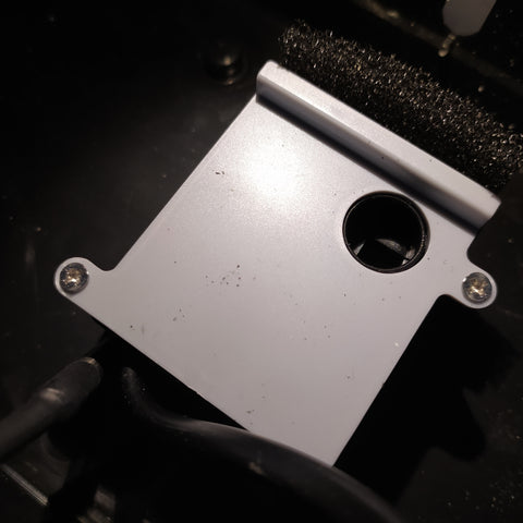
The brightness sensor is screwed into the brackets. The lines for the pump, the brightness sensor, the water temperature sensor and the conductivity sensor can be led into the device box by the openings at the top. The sensor for conductivity is inserted into the bracket after installation. The waterproof temperature sensor is simply placed in the water tub.


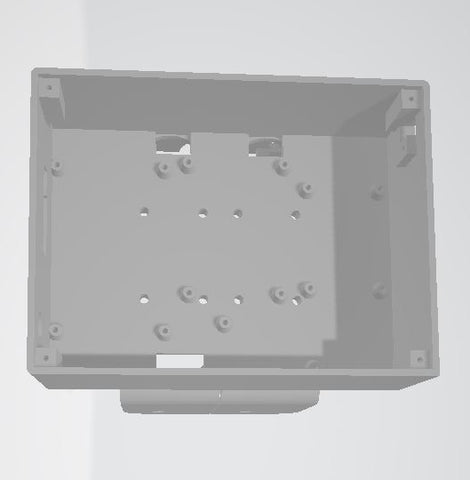
Fastening feet for the individual modules are available in the device box. As the figure shows, these are installed. The climate sensor HTU21 is attached to the right above the hole. The socket for the supply voltage is screwed into the wall at the bottom left. The wiring takes place at the end.

The complete electronics can now be hung in the edge of the water basin and screwed on. After a functional test, the lid is put on and screwed.

Have fun planting and harvesting.


7 comments
Gerald Lechner
@Norbert H.: Die Maximalwerte können im File index.h in den Zeilen 300 bis 323 verändert werden.
Mario K.
Vielen Dank für diese Projekt-Dokumentation.
Ich habe jedoch bei der Umsetzung ein Problem. In der WEB-Oberfläche und auch in der App werden die aktuellen Werte der Sensoren HTU21 und BH1750 nicht angezeigt. Die Sensoren sind definitiv richtig angeschlossen, was könnte die Ursache sein?
Für jede Information wäre ich dankbar, da ich im Frühjahr 2025 eine größere Anlage mit dieser Technik in Betrieb nehmen möchte.
Ich wünsche allen Leuten vom AZ-Delivery-Team und auch den kommentierenden Leuten hier ein guten neues Jahr!
Gruß Mario
Norbert H.
Hallo,
erstmal danke für diesen Beitrag. Habe es im Einsatz und bin zufrieden.
Lediglich kann ich beim Pumpenintervall höchstens 23 min. einstellen.
Ist das so gewollt?
Gerald Lechner
@Lukas: Das ist kein Potentiometer sondern einfach die Buchse für das Netzteil. Das kann man am Foto schlecht erkennen. Der Stepdown Wandler verträgt bis zu 25V.
Lukas
Hallo,
auf dem Schaltbild sieht man einen Potentiometer oberhalb des Umwandlers. Ist dieser da, um die Eingangsspannung zu regulieren?
Lisa C.
Hallo,
vielen Dank für diese äußerst nützlichen Informationen.
@Roland M. In der Schule wird so ein Projekt durchaus ausgeführt und Websites wie diese helfe uns sehr bei der Arbeit. :)
Roland M.
Hallo,
guter Beitrag, ich frage mich nur wer sowas nachbaut. Das ist schon sehr speziell und individuell.