The contribution is also available as a PDF document.
Color recognition sensors use photo dijung as a converter that pass on their tension to an analog-digital converter (AKA ADC). In the case of a TCS3200, four ADC inputs for red, green, blue and clearly have to take over the signals on the controller.
The change that I take under the Micropython magnifying glass does the change itself and also offers various extras such as reinforcement setting (PGA = programmable gain amplifier), area limitation, interrupt exit, area crossing, integration time setting, statemachine, single and continuous fashion, Swireless LED for lighting and the TCS3472 offers an I2C bus, through which the measured values get to the ESP32. Became curious? Then just come along with a discovery tour
Micropython on the ESP32 and ESP8266
today
TCS3472 - color detection sensor with i2c
We come to the hardware. As the head of the project, I use an ESP32, but an ESP8266 does it too, I only need a color detection module and an OLED display. As always, the circuit is set up on a Breadboard with several jumper cables.
Hardware
|
1 |
ESP32 Dev Kit C V4 unplacerated or |
|
1 |
Nodemcu Lua Amica Module V2 ESP8266 ESP-12F WiFi or |
|
1 |
|
|
1 |
|
|
1 |
The software
For flashing and the programming of the ESP32:
Thonny or
Used firmware for the ESP8266:
Used firmware for the ESP32:
The Micropython programs for the project:
SSD1306.PY Hardware driver for the OLED display
oled.py API for the OLED display
tcs3472.py Hardware driver for the color module
colorcheck.py Demo program
Micropython - Language - Modules and Programs
To install Thonny you will find one here Detailed instructions (English version). There is also a description of how the Micropython firmware (As of 18.06.2022) on the ESP chip burned becomes.
Micropython is an interpreter language. The main difference to the Arduino IDE, where you always flash entire programs, is that you only have to flash the Micropython firmware once on the ESP32 so that the controller understands Micropython instructions. You can use Thonny, µpycraft, or ESPTOOL.PY. For Thonny I have the process here described.
As soon as the firmware has flashed, you can easily talk to your controller in a dialogue, test individual commands and see the answer immediately without having to compile and transmit an entire program beforehand. That is exactly what bothers me about the Arduino IDE. You simply save an enormous time if you can check simple tests of the syntax and hardware to try out and refine functions and entire program parts via the command line before knitting a program from it. For this purpose, I always like to create small test programs. As a kind of macro, they summarize recurring commands. Whole applications then develop from such program fragments.
Autostart
If the program is to start autonomously by switching on the controller, copy the program text into a newly created blank tile. Save this file under boot.py in WorkSpace and upload it to the ESP chip. The program starts automatically the next time the reset or switching is on.
Test programs
Programs from the current editor window in the Thonny-IDE are started manually via the F5 button. This can be done faster than the mouse click on the start button, or via the menu run. Only the modules used in the program must be in the flash of the ESP32.
In between, Arduino id again?
Should you later use the controller together with the Arduino IDE, just flash the program in the usual way. However, the ESP32/ESP8266 then forgot that it has ever spoken Micropython. Conversely, any espressif chip that contains a compiled program from the Arduino IDE or AT-Firmware or Lua or ... can be easily provided with the Micropython firmware. The process is always here described.
Signals on the I2C bus
How a transmission works on the I2C bus and how the signal sequence looks, you can do in my post-Mammut matrix display part 2 read. I used their Interesting little tool, with which you can get and analyze the i2C bus signals on your PC.
The TCS3472 sensor and its module
Unlike the TCS3200, which releases its 4 color channels red, green, blue, and clearly as analog stresses, the TCS3472 delivers its information via the I2C bus digitally.
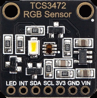
Image 1: TCS3472
In addition, the LED can be via the input LED switch (high-active). Based on the English Osram data sheets I have put together my Micropython module, whose methods I will describe below.
Now first the circuit for the experiments.
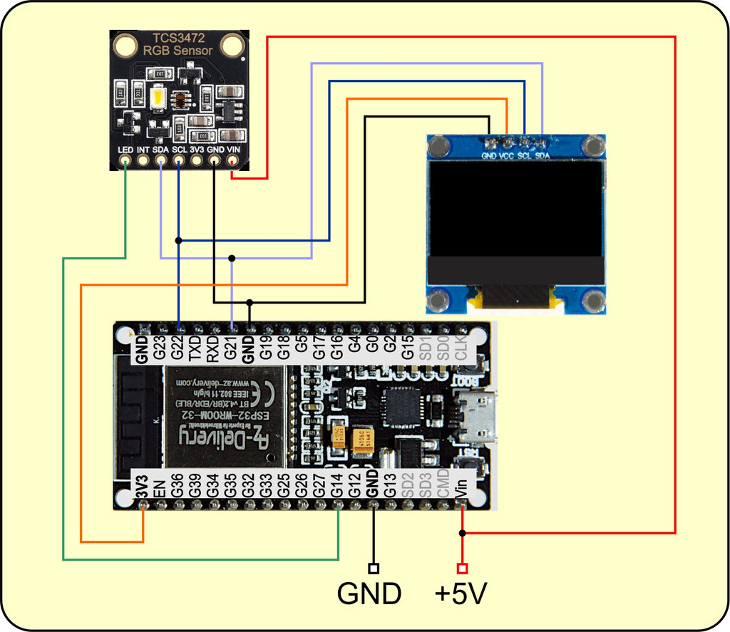
Image 2: circuit with ESP32
A state machine works in the TCS3472 that controls the course of the individual work steps. It can be influenced in some places from the outside. The signals of the four color channels reach integration via amplifier levels ADC converter. The reinforcements adjustable in four stages, as well as the integration time, both influence the value that finally ends up in the individual color remitters. Calculating the values for the integration time is somewhat exotic, as is scratched around the head on the left ear with the right hand. The situation is similar to the calculation of the waiting time between individual measurements in permanent run mode. The following illustration of the state machine can be found in the datasheet on page 17.
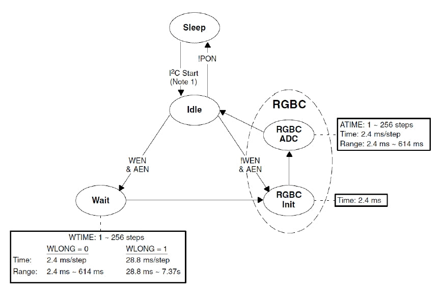
Image 3: Diagram of the Statemachine
On the calculation of the values for the Atime-Register through which the integration time is set, I go down below.
The module begins with two imports and a long list of declarations of the names for registers, masks, and so on in class TCS3472.
# tcs3472.py
From time import Sleep_ms
From machine import Pin code
class TCS3472:
Hwad = const(0x29)
Enable = const(0x00)
Atime = const(0x01) # 256 - Integration Time / 2.4 ms
Wime = const(0x03)
Ailtl = const(0x04)
Ailth = const(0x05)
Aihtl = const(0x06)
Aihth = const(0x07)
Pers = const(0x0c)
Config = const(0x0d)
Control= const(0x0f)
ID = const(0x12)
STATUS = const(0x13)
Clear = const(0x14)
Clearh = const(0x15)
Redl = const(0x16)
Redh = const(0x17)
Greenl = const(0x18)
Greenh = const(0x19)
Blade = const(0x1a)
Blue = const(0x1b)
CMD = const(0x80) # 1 SFUNC; 0 Regad
Autoinc= const(0x20)
Type=const(0x60)
Sfunc = const(0x60)
Adrmask= const(0x1f)
Cciclr = const(0x06)
Aia = const(0x10) # ADC-IRQ ENABLE
WHOM = const(0x08) # Wait Enabble
Aen = const(0x02) # ADC Enable
Pon = const(0x01) # Power on
Wlong = const(0x01) # 256 - Wait Time / 2.4ms
Gainx1 = const(0x00)
Gainx4 = const(0x01)
Gainx16= const(0x02)
Gainx60= const(0x03)
Gain=["X1","X4","X16","X60"]
Aintmask=const(1<<4)
Avalid mask=const(0x01)
PART = {0x44: "TCS34725",
0x4d: "TCS34727" }
Persist= {0:"Every",
1: 1,
2: 2,
3: 3,
4: 5,
5: 10,
6: 15,
7: 20,
8: 25,
9: 30,
10: 35,
11: 40,
12: 45,
13: 50,
14: 55,
15: 60}
Right at the beginning is the seven-bit hardware address of the TCS3472, which 0x29. Some Dictionaries (Dict), are used for plain text feedback from register content.
The method __init__() represents the constructor, which is called by TCS3472 () in the overarching program to create a TCS3472 instance (AKA object).
    def __init__(self, I2C, Itime=100,
                 Wime=3, gain=Gainx1, LED=14):
        self.I2C=I2C
        self.Itime=Itime
        self.Atime=255
        self.Wime=255
        self.Again=gain
        self.Wlong=0
        self.LED=Pin code(LED,Pin code.OUT,value=0)
        self.LED.value(0)
        self.running=False
        self.wake up()
        print("Constructor of TCS3472 class")
        print("Integration Time",self.slat(Itime),"MS")
        self.setwime(Wime)
        print("Wait Time",self.fuck(),"MS")
        self.setgain(gain)
        print("Gain is",self.Gain[self.getgain()])
        print("Chip is a",self.Getid())
When calling, an I2C object must be on the position parameter I2C to be handed over. This object is generated in the main program in accordance with the controller used. More on this in the sample program. All other parameters are optional and with default values.
I create some attributes that I will go into when discussing the respective routines. The pin object LED is used using the LED Pin number handed over and brought to GND potential. This deletes the LED on the BOB (Aka Break Out Board) of the TCS3472.
The method wake up() Brings the TCS3472 from Sleep mode to the Idle mode, from which measurements are started. The arguments for the integration time, the waiting time, and the reinforcement factor go to the TCS3472 and are issued in the terminal. The method Getid() delivers the type of chip. A TCS34725 tolerates up to 3.6V operating voltage, and the present TCS34727, on the other hand, only 3.3V. However, this does not have to interest us because a tension controller lives on the board, which can be loaded with 3.3V to 5V.
Four routines follow that serve to send and receive data and obey the I2C protocol of the TCS3472 shown in the data sheet (page 19). After that, a transfer must be submitted to a command byte, which includes the registered address, among other things. In the event of register access, the command bit (MSB = Bit 7) must also be set. This happens through ornament With the constant CMD. The Payoad is bound to an object that meets the buffer protocol. So I create the bytearar buf And fill the elements with my data. data is limited to the scope of bytes. writeto() sends the array to TCS3472. The auto-infrement bit is switched off because it is not explicitly set.
    def writebyte(self, ADR, data):
        buf=bytearar(2)
        buf[1]=data & 0xff #
        buf[0]= ADR | CMD
        self.I2C.writeto(Hwad,buf)
Works similarly writeword(), just that two data bytes are to be sent here. The 16-bit word is through Fierce With 0xff and right-hand pushing by 8 bit positions into a low-byte and a high-byte. The auto-infrement (Autoinc = 0x20) is also switched on in the command byte so that the bytes are pushed into consecutive registers. Autoinc is missing from Ornament, then stands in buf[0] In Bits 5 and 6 two zeros. This means that the same register is always addressed for repeated reading access.
    def writeword(self, ADR, data):
        buf=bytearar(3)
        buf[1]=data & 0xff #
        buf[2]=data >> 8   # High-byte First (Big Endian)
        buf[0]= Autoinc | ADR | CMD
        self.I2C.writeto(Hwad,buf)
The method reap() reads a byte from the ADR handed in. The bytearar buf With just one element, its purpose fulfills both when sending the registered address in the command byte and reading the value. It is not returned to the buffer, but the content of the zero element, i.e. a numerical value.
    def reap(self, ADR): #Register address
        buf=bytearar(1)
        buf[0]= ADR | CMD
        self.I2C.writeto(Hwad,buf)
        buf=self.I2C.readfom(Hwad,1)
        return buf[0]
readword() Reads a 16-bit value from the address in ADR one and works a little tricky. I only need one byte to send the address but for the reception two. So that I can get by with just one bytearar, I shipped CMD-bit, auto inc, and the address in buf[0] And then only send this part of the Array Buf [0: 1]. I would bufSend [0] I would get an error message because then a numerical value would be sent, the type of which is intimately not built on the buffer protocol. The following entries in Replpl make it clear.
>>> buf=bytearar(2)
>>> buf[0] = 0B10111010
>>> buf[0]
186
>>> buf[0:1]
bytearar(B '\ XBA')
>>> type(buf[0])
<class 'Int'>
    def readword(self, ADR): #Register address
        buf=bytearar(2)
        buf[0]=Autoinc | ADR | CMD
        self.I2C.writeto(Hwad,buf[0:1])
        buf=self.I2C.readfom(Hwad,2)
        return buf[0] | buf[1] << 8
There is not much to say about the following nine methods. You use the methods Readbye () and Readword ()to read the register content corresponding to the name. As an example, I grab title() and fuck() out of here.
    def gestatus(self):
        return self.reap(STATUS)

    def Getenable(self):
        return self.reap(Enable)

    def tattime(self):
        return self.reap(Atime)

    def title(self):
        self.Itime=intimately(2.4*(256-self.tattime()))
        return self.Itime

    def fuck(self):
        return 2.4*(256-self.reap(Wime))

    def getgain(self):
        return self.reap(Control)

    def Getid(self):
        return self.PART[self.reap(ID)]

    def gut(self):
        self.Fieldval=self.reap(Pers)
        return self.Persist[self.Fieldval]

    def Getthresholds(self):
        low=self.readword(Ailtl)
        high=self.readword(Aihtl)
        return low,high
The registry Atime Contains a byte value that contains the duration of the time window in which the signals are cumulated by the photodiodes. The calculation of the atime value takes place according to the following formula:
Atime = 256 − integration Time / 2.4 MS (formula 1)
Integration time Specifies the time duration in milliseconds. The shortest integration time is 2.4 ms the longest is 256 • 2.4 ms = 614 ms. The atime value is probably counted in a step up to the overflow of the 8-bite register. After 255 comes 0 and the integration process stops.
To get the integration time must (Formula 1) after Integration time is dissolved, this is exactly what the method uses title().
integration Time = 2.4 MS × (256 − Atime) (formula 2)
In the value in Wime, The waiting time is between two measurements. It is calculated similarly to Atime, provided the value of Wlong = 0 is. If Wlong = 1, then the waiting time of 2.4ms to 614ms is still to be multiplied by factor 12 and is then in the range between 28.8ms and 7.37 seconds.
For the Getxxxx () methods, the corresponding setxxxx () methods are of course a counterpart.
    def Setthresholds(self,low=0,high=0):
        self.writeword(Ailtl,low)
        self.writeword(Aihtl,high)
With Setthresholds() I can set limit values, if the sub- or exceeding a level change at the connection Intimately is triggered, provided that by setting the bits Aia is approved in the Enable Register.
    def setgain(self,Val):
        assert Val in range(4)
        self.gain=Val
        self.writebyte(Control,Val)
With assert, I check whether the value in Val is in the correct area 0..3. The upper limit in Micropython is usually not in the interval. The subtleties of the calculation of Atime you already know. If at intimate has not been handed over many times of 2.4, the return value of the function deviates slat() from the handover.
    def slat(self,intimate):
        self.Atime=256-intimately(intimate/2.4)
        self.writebyte(Atime, self.Atime)
        self.Itime=intimately(2.4*(256-self.tattime()))
        return self.Itime
At setwaittime() of course, the area is also checked first. Wlong must receive the value 1 if the time duration in waittime is larger than 614, otherwise, a 0 will be written in the register.
    def setwime(self,waittime):
        assert 2 < waittime <= 7370
        IF waittime > 614:
            self.setwlong(1)
            WT = waittime / 12
        Else:
            self.setwlong(0)
            WT = waittime
        self.Wime=256-intimately(WT/12*5)
        self.writebyte(Wime, self.Wime)

    def setwlong(self, wlong):
        assert wlong in range(2)
        self.Wlong=wlong
        self.writebyte(Config,wlong)
The value in the Perse tab (0… 15) determines how many consecutive measurements must be outside of the threshold area so that an interrupt is triggered. The Dict Persist knows the number of values in Pers.
    def setpersistance(self,Val):
        assert Val in self.Persist.value()
        for K,V in self.Persist.items():
            IF Val == V:
                self.Fieldval= K
                self.writebyte(Pers,K)
                return
The Enable-Tristers 0x00 contains three-bit flags that influence the state machine, Pon, WHOM, and Aen. The diagram of the same, in Image 3, tells us that the TCS3472 after receiving a start condition on the I2C bus in the Idle-Status changes. If in Pon = 1, then the further behavior depends on Aen and WHOM away. But at this point Pon = 0, then the TCS3472 returns to the Sleep-Status back. So to wake up must Pon to 1 to 1, which makes the method wake up() that in turn set(pon = 1) calls.
    def wake up(self):
        self.set(pon=1) # Idle state
        Sleep_ms(3)
        self.running=True
    def set(self, aia=None,
                        whom=None,
                        aen=None,
                        pon=None):
        enable=self.reap(Enable)
        IF aia is need None:
            assert aia in [0,1]
            enable &= (255-Aia)
            enable |= (aia << 4)
        IF whom is need None:
            assert whom in [0,1]
            enable &= (255-WHOM)
            enable |= (whom <<3)
        IF aen is need None:
            assert aen in [0,1]
            enable &= (255-Aen)
            enable |= (aen << 1)
        IF pon is need None:
            assert pon in [0,1]
            enable &= (255-Pon)
            enable |= pon
        self.writebyte(Enable,enable)
        return enable
set() is able to set all four flags through the passed parameters (parameters = 1) or to reset (parameter = 0). In all cases, the flag is reset first and then the argument 0 or 1 is pushed to the corresponding bit position. Because Micropython does not have an operator to form the compensation, the formation of the difference 255 - flagbyte must compensate for the defect. Parameters for which no value is handed over are left out because they have the default value of None.
The method tosleep() is the counterpart to awakening. I have the value of the Enable Register read, delete Pon and Aen in the manner just described, and write the byte back to the TCS3472.
    def tosleep(self):
        H=self.reap(Enable)
        self.writebyte(Enable,H & (255-(Pon+Aen)))
        self.running=False
The name is the program, and the routine starts single() An individual measurement starts. The TCS3472 is woken up to be on the safe side, then I switch on the ADCs by Aen on 1 set. The TCS3472 needs 3ms for this process, and I also let the ESP32 sleep on until the integration period has expired.
Then I bring in the color values trawval() off and bring the TCS3472 into the idle status before I have the tufa returned.
    def start single(self):
        self.wake up()
        self.set(aen=1) # Idle and adc on
        Sleep_ms(3) # WAIT FOR Initialization
        Sleep_ms(intimately((256-self.Atime)*12/5)+1) # Conversion Time
        vals=self.trawval()
        self.set(pon=1,aen=0)
        return vals
A permanent running measurement is with begin() toasted. After the mandatory waking up, I put the waiting time in milliseconds between the measurements on the handed-over argument value in Wime. After setting the three control flags at 1, I let the ESP32 miss the waiting time and duration of change. To pick up the values is trawval() responsible, the user is responsible for compliance with the latencies.
    def begin(self,Wime):
        self.wake up()
        self.setwime(Wime)
        self.writebyte(Enable, WHOM | Pon | Aen) # loop
        Sleep_ms(intimately(self.fuck()))
        Sleep_ms(self.title())
    def trawval(self):
        self.clear= self.readword(Clear)
        self.red  = self.readword(Redl)
        self.green= self.readword(Greenl)
        self.blue = self.readword(Blade)
        return self.clear,self.red,self.green,self.blue
The data sheet recommends not reading the color values by the way, but as Word. That makes the method readword(), which also returns the 16-bit value. As soon as the low byte is read, the high byte is blocked so that it cannot be overwritten by a new measurement value that has arrived in the meantime.
I can use the continuous run Stop() end. The routine simply sets the flags Aen and WE back. The TCS3472 then remains in idle fashion.
    def Stop(self):
        self.set(aen=0, whom=0)
The color braw values are the country of the ADCs and give a rough overview. It is better to refer the values to the overall level that the clear photodiodes deliver. The other colors must occur in this. Except for small deviations, R + G + B = Clear, 177 + 56 + 38 = 271 ≈ 268. An orange paper was tested. The method trigger() does the conversion of the country in RGB values and standardizes them to the range from 0 to 255. The IF construction prevents one Zerodivisor. A RGBTupel.
    def trigger(self):
        C,r,G,B=self.start single()
        IF C==0:
            r,G,B=0,0,0
        Else:
            r = intimately(r/C*255+0.5)
            G = intimately(G/C*255+0.5)
            B = intimately(B/C*255+0.5)
        return r,G,B
The Routine uses the RGB values calcct() to calculate the Correlated Color temperatures according to the formulas of McCamy.
    def calcct(self,r,G,B):
        IF r==0 and G==0 and B==0:
            return 0
        Else:
            X = -0.14282 * r + 1.54924 * G - 0.95641 * B
            Y = -0.32466 * r + 1.57837 * G - 0.73191 * B
            Z = -0.68202 * r + 0.77073 * G + 0.56332 * B
            XC = X/(X+Y+Z)
            yc = Y/(X+Y+Z)
            n = (XC-0.3320)/(0.1858-yc)
            CCT=449.0*(n**3) + 3525.0*(n**2) + \
                6823.3*n + 5520.33
            return intimately(CCT)
If the clear value is outside of the area set with Threshold, an interrupt can be triggered on the ESP32 if the line Int am TCS3472 is connected to an interruptable input of the controller and the flag Aia is set in the Enable Register. The method clear() reset the IRQ.
    def ClearCleahannelirq(self):
        buf=bytearar(1)
        buf[0]=Sfunc | Cciclr | CMD
        self.I2C.writeto(Hwad,buf)
A method with a triple effect comes at the end. The method LED() switches the LED on or off on the TCS3472 bob, depending on the argument, a 1 or a 0 is handed over as an argument. If no argument is handed over, then will Val be placed on the default value of none and then returned to the condition of the LED.
    def LED(self,Val=None):
        IF Val is need None:
            self.LED.value(Val)
        Else:
            return self.LED.value()
A whole series of Get and Set procedures can be summarized in this way. Do you want to try it out? Homework until next time?
Of course, we also want to test the new module on the object. Have you already built the circuit? Here is the test program.!
# Colorcheck.py
From TCS3472 import TCS3472
From machine import Pin code, Softi2c
From OLED import OLED
import sys
From time import sleep
IF sys.platform == "ESP8266":
I2C=Softi2c(scl=Pin code(5),sda=Pin code(4))
elif sys.platform == "ESP32":
I2C=Softi2c(scl=Pin code(22),sda=Pin code(21))
Else:
raise Runtime("Unknown Port")
LED=14
TCS=TCS3472(I2C,LED=LED)
D=OLED(I2C)
D.clearall()
D.contrast(255)
D.writer("Color Check",0,0)
sleep(3)
TCS.LED(1)
button=Pin code(0,Pin code.IN,Pin code.Pull_up)
while 1:
clear,red,green,blue=TCS.start single()
D.writer("Clear: {} cnts".format(clear),0,1)
D.writer("Red: {} cnts".format(red),0,2)
D.writer("Green: {} cnts".format(green),0,3)
D.writer("Blue: {} cnts".format(blue),0,4)
r,G,B=TCS.trigger()
CCT=TCS.calcct(r,G,B)
D.writer("CCT: {} K".format(CCT),0,5)
sleep(1)
IF button.value() == 0:
D.clearft(0,5,15,5)
D.writer("Canceelled",0,5)
sys.exit()
According to the imports, the program determines the controller type and sets the i2C bus to the corresponding pins. A TCS3472 object is instantiated, as is the OLED display. In the While loop, I get the colorful values and spend them on the display. Then the RGB values are calculated and then the color temperature. Finally, the flash key is queried and the program is ended properly if it is pressed.
Even after the end of the program, the methods of the TCS3472 module are still known to the controller. You can now try all routines in the THONNY terminal area.
LED out of:
>>> TCS.LED(0)
LED Interrogate
>>> TCS.LED()
0
Reinforcement on 4-academic subject
>>> TCS.setgain(TCS.Gainx4)
Continuous run start with smallest waiting period
>>> TCS.begin(2)
Traceback (custody recent call load):
File "" , line 1, in <modules>
File "TCS3472.PY", line 230, in begin
File "TCS3472.PY", line 164, in setwime
Assertion:
>>> TCS.begin(3)
>>> TCS.trawval()
(184, 85, 62, 37)
>>> TCS.trawval()
(53, 29, 14, 3)
>>> TCS.trawval()
(187, 87, 63, 37)
>>> TCS.Stop()
>>> TCS.trawval()
(185, 85, 62, 37)
>>> TCS.trawval()
(185, 85, 62, 37)
>>> TCS.trawval()
(185, 85, 62, 37)
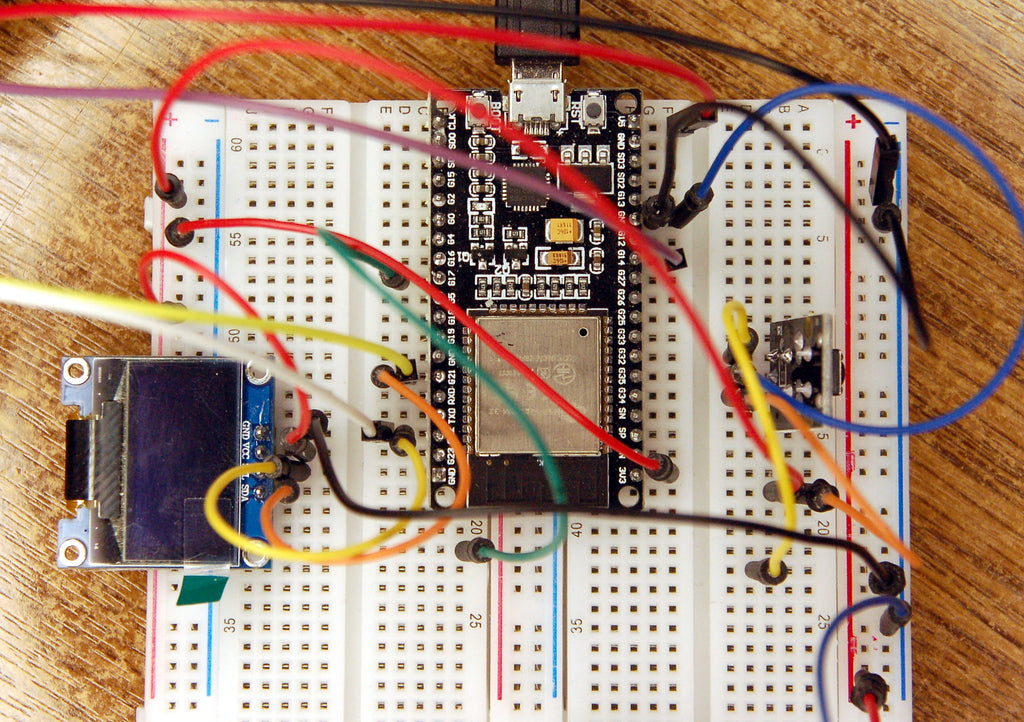
Image 4: The circuit to the project
In the next episode, we will compile the TCS3472 module. This can be done in Windows and of course in Linux. Until then!


