This article was provided by our guest author Matteo Trovò:
Electronic sensors are parts of many digital devices that we use every day, like our smartphones, our computers, or our cars. A sensor is basically a device that collects some information of any kind (usually a physical quantity) which can then be used by a computing unit to take any kind of decision and interact consequently in the physical world. Some real-world examples can be the accelerometers which are mounted on every smartphone and which basically allow the screen visualization to be properly oriented every time we move the phone or for example the oil pressure sensor of a car, which can help diagnose any motor problem.
Another interesting example is sensors used for environmental monitoring. Environmental monitoring consists of any kind of data logging in regards to a specific environment, which usually comprehends temperatures, pressures, humidity, and so on, which can relate to a local environment, like our home, or a remote environment, intended as any remote place, outside our home network.
In this article we are going to see this later example and how it is possible to connect our temperature sensor realized in the previous article: Temperature measurement? Never so easy with STM32 and MCP9808! with a SIM800L GSM cellular modem, to make a remote temperature sensor, which can be read through SMS.
But what is a cellular modem? This will be explained in the next chapter.
What is a cellular modem?
A cellular modem module is an integrated component that is used in all the cases in which cellular communication is necessary, like, for example, our smartphones. With a cellular modem is basically possible to send and receive SMS, doing phone calls, and even navigate on the internet.
There are several module types available on the market, based on different mobile communications technologies, like 2G, 3G, or 4G (Table 1).

Table 1 – Some of the older and newer mobile telephone technologies.
These modules can be usually easily interfaced with every microcontroller, using interfaces like UART or SPI.
While for GSM and GPRS modems, UART is still the most used choice, since a small data rate is expected, SPI remains the most used choice for LTE modems, where high performances are requested.
Communication to the cellular modem is done through a specific string-based protocol, named AT commands. A brief explanation of these commands will be given in another chapter.
Usually, a cellular modem includes the complete software stack for the telephone section, SMS handling, and internet connection, simplifying as much as possible the integration with embedded systems.
Let’s now have a deeper look at the modem model that we are going to use for this project, the SIM800L.
SIM800L module modem
SIM800L is a very known and common cellular modem module, which can be really often seen on embedded system projects, where a phone/internet connection is required and no other networks are available (e.g., Wi-Fi).
The module is very known among professionals and hobbyists and can be easily bought from several microelectronics vendors on the internet.
Here follows a picture of the module, of both top and bottom views (Image 1):

Image 1 -SIM800L Module kit, top and bottom view
As is possible to see from the picture, the cellular modem module is soldered over a small evaluation board, where pins can be accessed through the side pin strips. Not all the module pins have been connected for easy access, but only a small subset allows us to use the basic modem functionalities since the whole number of pins is very high. Two different antennas are included in the kit. From the bottom view can be seen the slot where the SIM card must be inserted. Cellular modules require a SIM card like the same one we use on our smartphones. Any working SIM card with enough credit for basic operation can be used here. Please note that the slot is suitable for hosting micro-SIM card format only, but adapters can be easily found.
Here follows a macro-schematic of the evaluation board from AZ delivery, showing the pinout (Image 2):

Image 2 – Pinout of the AZ Delivery SIM800L evaluation board
The module will be interfaced to an STM32 using a classical UART, through AT commands. The pins for the UART are the RXD and TXD.
A speaker can be connected with a microphone, in order to be able to make and receive calls. The speaker can be connected to SPKP and SPKN pins, while the microphone can be connected to MICN and MICP pins. These two interfaces are differential. The antenna can be connected to the ANT input. Relevant to mention is that the cellular modem works with a nominal voltage of around 4 volts (VCC-GND). The modem is quite demanding in terms of absorbed current, therefore the module can’t be supplied directly from the evaluation board and an external power supply is necessary. A power supply able to deliver peaks of 2 Amperes at 4 volts would be enough.
Modem AT Commands
AT commands (or Hayes commands) consists of a command set made up of a series of small text strings, which combined, can be used to trigger the execution of specific operations on modems, like phone calls, SMS sending and receiving, or data transmission over internet.
A very good introduction to the topic can be found here: https://en.wikipedia.org/wiki/Hayes_command_set, while a complete command set valid for the SIM800L can be found here: https://www.elecrow.com/wiki/images/2/20/SIM800_Series_AT_Command_Manual_V1.09.pdf
Let’s start! Setup the hardware
After this introduction, we can now set up the hardware. The cellular modem will be connected to an STM32 Nucleo-64 evaluation board, for which a good introduction can be found already in this post: Using the USB Serial Port on the STM32 Nucleo-64 board.
In the following picture is possible to see the complete electrical schematic of our project (Image 3) and also a picture of my actual setup (Image 3).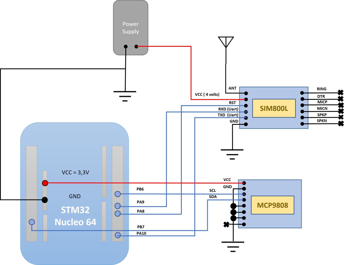 Image 3 – Electrical schematic of the remote sensor
The schematic is relatively simple and it uses two UARTs and one I2C. The I2C is used for reading the MCP9808 temperature sensor, one UART is used for debugging (Serial port), while the other is connected to the SIM800L modem. Relevant is the power connection of the modem, which must be provided from an external power supply at 4 volts, and the reset pin, which is used at startup to reset the modem before the initialization, which can be any free GPIO pin of the STM32. In my project, I configured it over the pin PA8.
Another relevant point is that all the involved grounds should be obviously connected together. (Eval board and external power supply).
Image 4 – Hardware setup
Get the software
You can now download the whole project from GitHub here: https://github.com/EmbeddedEspresso/remote_temp. This is an STM32CubeIDE project, so you can compile it and start debugging it over the STM32.
The software is organized in several state machines, one for every specific handling, like for example I2C or UART modem communication. Here follows a block schematic of the software and a brief description of every handler (Image 5).

Image 5 – Software architecture
All the state machines are initialized and executed from the main, as shown in the following code snippet of the main.c file:
/* Initialize all the software state machines */
UartModemHdlrInit(&huart1);
UartDebugHdlrInit(&huart2);
ModemHdlrInit();
DebugHdlrInit();
AppHdlrInit();
TempSensorHdlrInit();
while (1)
{
/* Main software handler */
UartModemHdlrRun();
UartDebugHdlrRun();
ModemHdlrRun();
DebugHdlrRun();
AppHdlrRun();
LedAliveRun();
TempSensorHdlrRun();
}
All software modules are state machine based, as previously mentioned, designed to offer a re-entrant and non-blocking implementation.
The execution time of every “Run” function call is the smallest possible since all the states are small and designed to not incur any waiting loop mechanism (e.g. non-blocking hardware access).
Modem and Debug UART drivers
UART drivers have been completely rewritten, therefore the standard-generated STM HAL drivers have not been used. The reason for that was to obtain a non-blocking implementation, which could exploit polling as much as possible.
The UART used for debugging has a complete polling implementation, where every hardware access is handled through a specific switch case state, allowing a non-blocking re-entrant implementation; performance is not a must for this driver, therefore no particular care over-optimization has been given here.
The story is instead a bit different for the UART used for the modem communication: while the command sent from the microcontroller does not suffer in any case for performance issues, we cannot say the same for the received data from the Modem. The modem itself cannot be controlled by us in terms of generated data and it is also not possible to forecast at which point the modem will send any data, also because of unsolicited commands which are triggered usually by random events and not by a specific microcontroller request, therefore here an interrupt solution has been adopted (Image 6).

Image 6 – A driver implementation detail
The receiving buffer for the modem UART has also special handling, for ensuring fixed formatting of the received strings, automatically removing on reception every command separator a part from \r (\n, if present, will be automatically removed).
Modem handler
The modem handler consists of the complete Modem commands and initialization handling. This handler takes care of performing a complete modem initialization and handling every other command. It offers an interface based on several APIs to simplify integrations of upper functional layers.
The module is quite scalable, allowing you to easily add new commands or new APIs. Here follows a list of the offered APIs:
- ModemHdlrGetSignalLevel: allows to read the current signal reception level of the modem.
- ModemHdlrGetDateTime: allows to get the current date and time from the connected telephone cell.
- ModemHdlrSendSMS: Send an SMS to a specific number.
- ModemHdlrReadSMS: Read a received SMS from the modem's local storage.
- ModemHdlrDeleteSMS: Delete a specific SMS or the whole SMS memory.
Debug handler

Temperature sensor handler
This is a simple module that handles the temperature sensor, including also the I2C communication. The used I2C drivers come from the STM HAL package and are therefore blocking during transmission and reception of data. While this would not be maybe the best solution for a final product, it can be safely used in our demo test, where all the execution timings for each task have been monitored. Once the temperature is sampled, a variable with the latest value is updated. The variable can be accessed from the other modules through a specific API: TempSensorGetValue.
Application handler

Test the GSM modem connectivity
As a first test, to prove that we realized the electronic circuit correctly, we will just test the connection with the cellular modem and then test if we can send or receive commands.

The solution is pretty easy and it basically consists of forwarding every received byte from the modem UART to the debug UART and vice versa.

Once the correct parameters are selected, like the right COM port or the right speed, we can click Open to start the serial port session.

Let’s now send some commands to the modem. We can start with the classical AT, which is basically used only for testing modem connection and then check the SIM Card status, to see if a PIN is required or not (Image 12):

As is possible to see from the picture, the modem answered positively to the command AT, with an OK and it answered with no errors also to the command “AT+CPIN?” which questions the SIM Card pin status. Apparently, the SIM Card does not require any pin code activation in this case and it can be used for SMS or Internet. We can now proceed with the next chapter and finally test the complete project.
Ready to test your GSM sensor?

During the initialization, many debug strings will be printed allowing us to understand the current software status. Relevant are the unsolicited “Call Ready” and “SMS Ready” which basically indicate to the software that the modem is ready to be used for SMS and calls.
In the meanwhile, also the temperature logging from the sensor is showed.

As soon as the incoming message is detected from the software (unsolicited +CMTI), the message is read and the content analyzed. If the content matches the string “Get Temperature”, then a new SMS is created with the current temperature as text and with the receiver phone number set at the same number as the requester.

Conclusion
This article shows how the SIM800L modem can be easily interfaced with an STM32 to make an SMS-based temperature sensor. Of course, SMS is no longer the most used data transmission technology but it is still a good solution, considering the relatively small data rate.
The SIM800L modem supports also a 2G internet connection, therefore a possible project extension would be to extend the Modem Handler adding support also to internet commands allowing to send of the temperature information directly to a server that can collect the data and offer a graph visualization interface.


