In the blog sequence to the Advent wreath calendar Worked the time measurement via an NTP server on the web or, if no WLAN was available, via the RTC (AKA Real Time Clock) on the ESP8266, which was used at the time. I had not made any examinations on the accuracy of the onboard clock. Now in retrospect, I did exactly that. Amazing results came to light that I do not want to withhold from them. Follow me on a journey through time
Micropython on the ESP32 and ESP8266
today
Watches, RTC, NTP, and Co.
So in advance, the RTC of the ESP8266 is junk in the least, when it comes to gear accuracy. I examined an ESP8266 D1 Mini Pro with an ESP8266 ex-controller. The deviation against the NTP time from the network is almost 2 minutes an hour, which is three-quarters of an hour a day that runs the RTC faster. The RTC of an ESP8266 12F (Node MCU V3) takes almost half an hour a day.
Because this cannot be a condition, I also included an external RTC with a battery buffer in my experiments. The advantages and disadvantages bring on the ESP8266. An available DS1302-BOB (Break Out Board) unfortunately does not listen to the I2C bus but needs its own serial bus with three lines, which of course occupy three GPIOs and they are not exactly lavish on the ESP8266. Of course, I needed a dedicated hardware driver for the chip, which I in the form of the module ds1302.py have built.
But the DS1302 comes up with much better accuracy. Here we speak of 8 to 10 seconds a day that the RTC of the chip is going. This is about 50 minutes a year, corresponds to the accuracy of a quartz train, and is bearable.
Of course, I also wanted to know how an ESP32 behaves in terms of time. So I let the same programs run on both the ESP8266 and the ESP32. I will tell you further what came out of here. Let's take a look at the hardware and software used in the experiments.
Hardware
|
1 |
ESP32 Dev Kit C V4 unplacerated or |
|
1 |
Nodemcu Lua Amica Module V2 ESP8266 ESP-12F WiFi or |
|
1 |
|
|
1 |
|
|
1 |
|
| 1 | DS1302 Serial Real Time Clock RTC real-time clock Clock module |
The software
For flashing and the programming of the ESP32:
Thonny or
Used firmware for the ESP8266:
Used firmware for the ESP32:
The micropython programs for the project:
ds1302.py Hardware driver for the DS1302
SSD1306.PY Hardware driver for the OLED display
oled.py API for the OLED display
DS1302 Set+Get.PY Program for the watch comparison NTP-RTC-DS1302
rtc set+get.py Program for the watch comparison NTP-RTC
Micropython - Language - Modules and Programs
To install Thonny you will find one here Detailed instructions (English version). There is also a description of how the Micropython firmware (As of 18.06.2022) on the ESP chip burned becomes.
Micropython is an interpreter language. The main difference to the Arduino IDE, where you always flash entire programs, is that you only have to flash the Micropython firmware once on the ESP32 so that the controller understands Micropython instructions. You can use Thonny, µpycraft, or ESPTOOL.PY. For Thonny I have the process here described.
As soon as the firmware has flashed, you can easily talk to your controller in a dialogue, test individual commands and see the answer immediately without having to compile and transmit an entire program beforehand. That is exactly what bothers me about the Arduino IDE. You simply save an enormous time if you can check simple tests of the syntax and hardware to try out and refine functions and entire program parts via the command line before knitting a program from it. For this purpose, I always like to create small test programs. As a kind of macro, they summarize recurring commands. Whole applications then develop from such program fragments.
Autostart
If the program is to start autonomously by switching on the controller, copy the program text into a newly created blank tile. Save this file under boot.py in WorkSpace and upload it to the ESP chip. The program starts automatically the next time the reset or switching is on.
Test programs
Programs from the current editor window in the Thonny-IDE are started manually via the F5 button. This can be done faster than the mouse click on the start button, or via the menu run. Only the modules used in the program must be in the flash of the ESP32.
In between, Arduino id again?
Should you later use the controller together with the Arduino IDE, just flash the program in the usual way. However, the ESP32/ESP8266 then forgot that it has ever spoken Micropython. Conversely, any espressif chip that contains a compiled program from the Arduino IDE or AT-Firmware or Lua or ... can be easily provided with the Micropython firmware. The process is always here described.
The time formats from NTP, RTC, and DS1302
Local time
On the ESP32/ESP8266, the era takes place in seconds from the beginning of the era. This is the 01.01.2000 with the ESP8266. You can verify this by in the Terminal window of Thonny from the module time the function local() call 0 seconds.
>>> import time
>>> time.local(0)
(2000, 1, 1, 0, 0, 0, 5, 1)
This function returns the date, 2000-01-01, and the time (00:00:00). The day of the week (5 = Saturday) and the number of the day of the year (1). The values are in one Tupel (narrow. Tulle) summarized. The order of the individual information is therefore as follows and also corresponds to that of the NTP format. Dow stands for Day of Week, and Doy for Day of Year.
Year, month, day, hours, minutes, seconds, Dow, Doy
In addition, an example illustrates the relationships. The function time() of the module time delivers the number of seconds since the era. The function local() converts this value into the date values of the tupel.
>>> time.time()
723460001
>>> time.local(723460001)
(2022, 12, 4, 9, 6, 41, 6, 338)
So it is 04.12.2022, 9:06:41 a.m. The 338th day of the year is a Sunday. The days of the week are counted from 0 = Monday to 6 = Sunday.
The Real Time Clock - the RTC module
The class RTC lives in the module machine.
>>> From machine import RTC
>>> RTC
<class 'RTC'>
It provides the method DateTime() available, which also returns a tupel with date and time values without parameters. However, the order of the parameters gives way from that of the function time.localime() away. The day of the week follows the date and the last parameter is not the day of the year but delivers the fractions of the second in milliseconds.
>>> RTC=RTC()
>>> RTC.DateTime()
(2022, 12, 4, 6, 9, 50, 50, 215)
If you hand over the method DateTime() On the other hand, a tuble of this form, then the information is converted into a second-time stamp, and the RTC is placed afterward. Weekend day and a fraction of seconds are handed over as 0.
>>> RTC.DateTime((2022, 12, 4, 0, 9, 6, 41, 0))
>>> RTC.DateTime()
(2022, 12, 4, 6, 9, 6, 42, 295)
To the RTC format that of time and NTP To compensate for use, I wrote two functions that I use in my programs. You set the existence of an RTC object with the name RTC Ahead and take over the recording of the time formats.
def truck():
        yr,mon,day,dow,horel,minute,sec,MS=RTC.DateTime()
        return(yr,mon,day,horel,minute,sec,dow,MS)

def STRTCTime(dt):
    y,Mo,day,H,M,S,dow,Doy=dt
    RTC.DateTime((y,Mo,day,0,H,M,S,0))
    # The RTC automatically synchronizes with UTC + time zone
    print("RTC Time Set to",RTC.DateTime())
truck() Get with rtc.dateTime() A tupel from the RTC, which I break into individual parts. This process means unzipping and can with tuels and List be performed. Then I put the values together again into a standard tupel that is returned.
In the function STRTCTime() I hand over a standard tupel that is also first unpacked into the individual values. I hand over a tupel with a changed order to the method rtc.dateTime() and set the onboard clock.
The Network Time Protocol NTP
To use NTP, I need a server on the net that supports this protocol. There are many of them. All manage time, similar to the Time module in seconds since the beginning of the era. However, this did not start on January 1, 2000, but on January 1, 1900. The constant Rtc.ntp_delta = 3155673600 invoices, which in the class ntpime is declared. When calling ntpTime.Time() This value is deducted from the value queried with the NTP server in order to get the ESP controller era. By calling time.localime (ntpTime.time ()) the second value is finally converted into the standard format.
What objects the module ntpime available, you can look at the Thonny object manager. There you can also find the URL with which the ESP8266/ESP32 connects: pool.ntp.org.
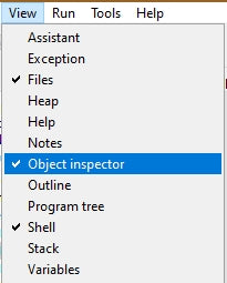
Image 1: Activate object inspector

Image 2: Objects of the NTPTime module
The module DS1302
The tabs of the DS1302 provide the daily and time data in BCD format the information is read out or set in a serial manner. You can find out how this works in this chapter.
In order to include the DS1302 in my attempts, I have based on the Data sheets of the DS1302 a module created, ds1302.py. It provides the corresponding methods for all essential tasks. The property of loading buffer battery cells was not implemented because only a lithium battery is used on the bob that cannot be loaded.
I start with the import of the class Pin code From the module machine. I assign names to the registration numbers of the DS1302, which simplifies the handling. They are stored as constants in the flash of the ESP8266/ESP32. The list of days Contains the daily figures from January to December. I need this list later to calculate the number of the current day as an eighth parameter, as with the NTC time format.
Then I declare the class DS1302, its constructor __init __ () With the PIN numbers handed over, the PIN objects for the cables DIO, CLK, and CS.
class DS1302:
    def __init__(self, CLK, dio, CS):
        self.CLK = Pin code(CLK,Pin code.OUT)
        self.dio = Pin code(dio)
        self.CS  = Pin code(CS,Pin code.OUT)
The two methods Dec2bcd() and BCD2dec() Complete the recoding from the decimal system into BCD format and vice versa. You can find out the background in the glossary.
    def Dec2bcd(self, data):
        return (data//10)<<4 | (data % 10)
The argument's tensions data I get through full-figure division Data // 10. I push them into the high-nibble of the result by four-bit positions. The Modulo 10 division remnants deliver one figure. This is Ordered with the previous result and is in the low-nibble of the result bytes.
    def BCD2dec(self, data):
        return (data >>4)*10 + (data & 0x0f)
I slide the high-nibble by 4-bit positions to the right and thus receive the number of times that is multiplied by 10 for the result. I get the one figure by masking the high-nibbles at Fierce With the mask 0B00001111 = 0x0f.
The function, forgiveness, wanted to say method because we are within a class and there you say about functions method. In the OOP (OOP AKA object-oriented programming), variables are also called attributes and the objects are also used as an instance.
So, the method writebyte() operates the lowest layer of the transmission. It pushes the individual bits via the data line, the LSBit (Least Significant Bit = low-quality bit) first. The data line dio is switched as output, the data byte is pushed to the right by 0 to 7-bit positions and then isolated the LSbit. This does a unanimous manner with the mask 0B00000001. Then the clock line is CLK Briefly brought back to 1 and immediately afterward. That happens eight times.
    def writebyte(self, data):
        self.dio.init(Pin code.OUT)
        for I in range(8):
            self.dio.value((data >> I) & 1)
            self.CLK.value(1)
            self.CLK.value(0)
reap() picks up a byte from the DS1302. The reception variable data I set to 0 and switch the data line dio on the entrance. Then I read the condition of the line and push it a bit by 0 to 8 positions to the left. The first bit, therefore, ends up in position 0, the last one as an MSbit (MOST Significant bit = high-quality bit) in position 7. A clock on the line CLK Requests the next bit from the DS1302.
    def reap(self):
        data = 0
        self.dio.init(Pin code.IN)
        for I in range(8):
            data = data | (self.dio.value() << I)
            self.CLK.value(1)
            self.CLK.value(0)
        return data
The next higher transmission layer sets the frame for a transfer. In order for the transmission to begin, the CS-Meadings (chip select) are set to 1. Then I send the address of the register to be spoken, and that of the method readreg() is handed over as an argument. Immediately afterward, the DS1302 transfers the tab, which I have with reap() pick up. The controller always provides the clock, he is the boss.
    def readreg(self, reg):
        self.CS.value(1)
        self.writebyte(reg)
        reg = self.reap()
        self.CS.value(0)
        return reg
The method writereg() Similarly, instead of receiving a byte, one is sent. In reg and data are handed over registration number and data byte.
    def writereg(self, reg, data):
        self.CS.value(1)
        self.writebyte(reg)
        self.writebyte(data)
        self.CS.value(0)
The top transmission layer regulates writing access to the DS1302. In order for a register to be described on the chip, this must Write-Protect-bit in register RWP be set to 0. Then I send the registration number and the database to then reactivate writing protection.
    def write(self, reg, data):
        self.writereg(RWP, 0)
        self.writereg(reg, data)
        self.writereg(RWP, 0x80)
Image 3 shows the division of the RTC registers of the DS1302. You can find the table on page 9 of the Datasheets.

Image 3: Register the landscape of the DS1302
CH (Clock Hold), bit 7 of the second register, stops the watch when it is set. The following two methods take over the control begin() and Stop().
def begin(self):
H = self.readreg(Rseecunde | 1)
self.write(Rseecunde, H & 0x7f)
def Stop(self):
H = self.readreg(Rseecunde | 1)
self.write(Rseecunde, H | 0x80)
Most of the other methods read the corresponding registers for seconds, minutes, etc. if they are accessed without an argument. If, on the other hand, a number is handed over, it is interpreted as a corresponding time or date value, checked or limited to valid values , and sent to the DS1302. To read the DS1302, the R/-W-Bit must be set to 1 in the address byte, to write to 0. The clock is addressed if the bit 6 RAM/-CK is also on 0. If it is set to 1, one of the 31 RAM bytes is addressed. More on that later.
    def second(self, second=None):
        IF second == None:
            return self.BCD2dec(self.readreg(Rseecunde | 1))%60
        Else:
            self.write(Rseecunde, self.Dec2bcd(second % 60))
The method DateTime(), called without an argument, returns a date-time tupel in a standard format. For this purpose, the individual registers are queried and composed into the tupel. For calculating the daily number in the year, the days before the current month are added up and then added to the month of the month. In the case of a leap year, the sum is increased by 1 if the month number is 3 or higher. The method checks whether a leap year is an available leap year(), then this is from this True returned.
def leap year(self, year):
SJ = ((year % 400) == 0) or \
((year % 4) == 0 and (year % 100) != 0)
return SJ
def DateTime(self, data=None, **further):
IF data == None:
J=self.year()
M=self.month()
D=self.MaTag()
Doy = 0
for n in range(M-1):
Doy += days[n]
Doy = Doy + D + 1 IF self.leap year(J)and M>2 \
Else Doy+D
self.hour(),
self.minute(),
self.second(),
self.dow(),Doy]
Else:
self.year(data[0])
self.month(data[1])
self.MaTag(data[2])
self.hour(data[3])
self.minute(data[4])
self.second(data[5])
self.dow(data[6])
In addition to the RTC, the DS1302 also provides 31 bytes also battery-buffered RAM memory. The content is therefore preserved even when the controller is switched off.
At this point, I go into the structure of the addressby of the DS1302 for more detail. You can find a display on page 5 of the Data sheets.

Image 4: The address byte of the DS1302
In addition to the address itself, the byte includes two tax bits. Bit 0 decides on reading access (RD/-WR = 1) or writing access (RD/-WR = 0). With Bit 6 I can control access to the RAM (RAM/-CK = 1) or to the RTC (RAM/-KCK = 0). Bit 7 must always be set to 1.
The addresses of the registers are already stated by the constants at the beginning of the module listing so that the RTC writing access to the second register, which is actually the register 0, 0x80 = 0B10000000 results and for reading access 0x81 = 0B10000001. Bit 6 must be set when accessing the RAM. The first RAM memory cell therefore has the address 0xc0 = 0b11000000 for writing access and 0xc1 = 0B11000001 when reading. While the registrar numbers at RTC are clearly assigned to a name, the RAM bytes must be addressed individually. This is done by adding the cell address from 0x00 to 0x1f to the basic address 0xC0, but not as a bit 0 to 4, but as a bit 1 to 5, as shown in Image 4. The cell number must therefore be pushed to the left by a bit position. For example, 0x14 becomes 0x28. In addition, a 1 must be added for reading access, 0x29. Because pushing has a lower priority as an arithmetic operation than addition, pushing must be completely clung by 1. All of this takes into account the method R.A.M(). In reg Is the number of the memory cell handed over, not their address! Missing the argument data When calling, then the contents of the cell are called up, otherwise the cell with the value in the data described.
    def R.A.M(self, reg, data=None):
        IF data == None:
            ADR=Rram start + ((reg % 31)<<1)  + 1
            print(hex(Rram start),hex(ADR))
            return self.readreg(ADR)
        Else:
            self.write(Rram start + ((reg % 31)<<1) + 0, data)
With the RAM memory in the DS1302, we have the option of revealing data about (almost) any time. The chip only suffers amnesia if the battery is empty or is removed.
Query an NTP server
WLAN access is required for contact with an NTP server. Two modules must at least be imported, network and ntpime, Plus a few functions. The program ntp_test.py demonstrates access to an NTP server, here pool.ntp.org. This URL is in the module ntpime already specified. For the rather simple access to the network time ntptime.time (), who gets the world time UTC in seconds, a comparatively huge overhead is required. Because the station interface of the ESP8266/ESP32 must be set up and a WLAN connection must be built up. Here is the listing:
# ntp_test.py
import ntpime AS NTP
import network
From time import sleep, local
timezone=1
# ************* Define WLAN access *****************
#
myssid="Here goes your ssid"
mypass="Here goes your password"
myport=9009
connect status = {
1000: "Stat_idle",
1001: "Stat_Connecting",
1010: "Stat_got_ip",
202: "Stat_wrong_Password",
201: "No ap found",
5: "Unknown",
0: "Stat_idle",
1: "Stat_Connecting",
5: "Stat_got_ip",
2: "Stat_wrong_Password",
3: "No ap found",
4: "Stat_Connect_Fail",
}
# ************* Man define *******************
#
def Time-out(T):
begin=Ticks_MS()
def compare():
return intimately(Ticks_MS()-begin) >= T
return compare
def hexmac(bytemac):
"""
The HexMac function takes the Mac address in the bytecode and
forms a string for the rehabilitation
"""
MacString =""
for I in range(0,len(bytemac)): # For all byte values
MacString += hex(bytemac[I])[2:] # String from 2 to the end
IF I <len(bytemac)-1 : # Delimiter
MacString +="-" # except for the last byte
return MacString
nic = network.WIRELESS INTERNET ACCESS(network.Ap_if) # AP interface object
nic.active(False) # Switch off safely
nic = network.WIRELESS INTERNET ACCESS(network.Sta_if) # Create WiFi object
nic.active(True) # Sta-object Nic
#
Mac = nic.config('Mac') # Call base Mac address and
mymac=hexmac(Mac) # convert into a hex digit sequence
print("Mac station: \ t"+mymac+"\ n") # spend
#
# Record connection with AP in the local network,
# If not yet connected
IF need nic.Isconnected():
# Connect to the AP in the local network and display status
nic.connect(myssid, mypass)
# Wait until the connection to the Accesspoint is
print("Connection status:", nic.Isconnected())
while (nic.status() != network.Stat_got_ip):
print(".",end='')
sleep(1)
# If connected, show connection status and config data
Nicstatus=nic.status()
print("\ nanation status:",connect status[Nicstatus])
Staconf = nic.ifconfig()
print("Sta-IP: \ t \ t",Staconf[0],"\ nsta-netmask: \ t",Staconf[1],\
"\ nsta-gateway: \ t",Staconf[2] ,sep='')
sleep(3)
while 1:
try:
Day=local(NTP.time()+timezone*3600)
print("NTP-Time",Day)
except:
print("Transfer error")
sleep(1)
After the start of the program, we will be informed of the MAC address of the controller's StA interfaces. This address must be entered in the WLAN router so that its bouncer also encloses the ESP32/ESP8266 into the establishment. If you are not known, stay outside. Incidentally, it is not a good idea to switch off the MAC filter in the WLAN router, precisely because then Hinz and Kunz can easily log in. Your router manual tells you where and how you can enter the Mac.
Mac station: D8-BF-C0-14-BA-6C
Runs somewhere in the LAN DHCP-Server, mostly this is the router itself, which provides the service, then the controller receives an IP address from it and we start the main loop. The NTP server is contacted there every second. For the received second value, we add up the offset through the time zone and let the tupel output.
Connecting status:  Stat_got_ip
Sta-IP:     10.0.1.215
Sta-Netmask:    255.255.255.0
Sta-Gateway:    10.0.1.20
NTP-Time        (2022, 12, 4, 14, 32, 41, 6, 338)
NTP-Time        (2022, 12, 4, 14, 32, 42, 6, 338)
NTP-Time        (2022, 12, 4, 14, 32, 43, 6, 338)
NTP-Time        (2022, 12, 4, 14, 32, 44, 6, 338)
NTP-Time        (2022, 12, 4, 14, 32, 45, 6, 338)
The watch comparison
This Base program we can now expand. I did this in this way that I initially installed an option through which the Symp32/ESP8266 on the board and the RTC of the DS1302 with the NTP time is carried out. I use the Flash key of the ESP32/ESP8266 - Nodemcu. The ESP8266 D1 Mini Pro does not have a flash key, so I had to give it a key module. So he is very happy.
So the program starts at the push of a button, the program starts without a button without synchronization. The request to activate keyboard can be requested via the OLED display. Now I can in a certain, through sleep() Adjustable interval, in the main loop, call up the NTP time and compare it with the on-board RTC and the DS1302. So I was able to determine the time deviations described at the beginning. What I found absolutely amazing was the fact that the RTC of the ESP32 only had a gear deviation of only +2 seconds a day!
The situation is quite different with the ESP8266. The program DS1302 Set+Get.PY I started synchronization at 11:40 a.m. An hour later there was already a deviation of +68 seconds! While the DS1302 does not differ significantly from the NTP time.
NTP-Time: 723382804
NTP-Time        (2022, 12, 3, 12, 40, 4, 5, 337)
RTC             (2022, 12, 3, 12, 41, 12, 5, 967)
DS1302 Time     [2022, 12, 3, 12, 40, 3, 5, 337]
Here are the circuits for the experiment.

Image 5: ESP8266 D1 Mini Pro in the test circuit

Image 6: ESP32 in the test circuit
And here is the listing of the program DS1302 Set+Get.PY. It can be used for ESP32 and ESP8266 equally without a change. There is also a emaciated version rtc set+get.py, in which the interactions with the DS1302 were removed. This allows only the RTC to be examined compared to the NTP time.
# DS1302 Set+Get.PY
# Pintranslator for ESP8266 boards
# Lua-Pins D0 D1 D2 D3 D4 D5 D6 D7 D8
# ESP8266 Pins 16 5 4 0 2 14 12 13 15
# SC SD
From machine import Pin code, Softi2c, RTC, Deepsleep
From time import sleep, time, local, Ticks_MS
import ntpime AS NTP
From OLED import OLED
import network
import sys
From DS1302 import DS1302
IF sys.platform == "ESP8266":
I2C=Softi2c(scl=Pin(5),sda=Pin(4))
elif sys.platform == "esp32":
i2c=SoftI2C(scl=Pin(22),sda=Pin(21))
else:
raise RuntimeError("Unknown Port")
d=OLED(i2c,heightw=64) # 128x32-Pixel-Display
d.clearFT(0,0,15,2)
d.writeAt("UHRENVERGLEICH",0,0)
d.writeAt("NTP-ZEIT",3,1)
d.writeAt("RTC+DS1302-ZEIT",0,2)
sleep(1)
d.clearFT(0,0,15,2)
timeZone=1
ds= DS1302(clk=13,dio=14,cs=12)
rtc=RTC()
taste=Pin(0,Pin.IN, Pin.PULL_UP)
# **************WLAN-Zugriff definieren*******************
#
mySSID="here goes your SSID"
myPass="here goes your password"
myPort=9009
connectStatus = {
1000: "STAT_IDLE",
1001: "STAT_CONNECTING",
1010: "STAT_GOT_IP",
202: "STAT_WRONG_PASSWORD",
201: "NO AP FOUND",
5: "UNKNOWN",
0: "STAT_IDLE",
1: "STAT_CONNECTING",
5: "STAT_GOT_IP",
2: "STAT_WRONG_PASSWORD",
3: "NO AP FOUND",
4: "STAT_CONNECT_FAIL",
}
# **************Funktionen definieren*********************
#
def TimeOut(t):
start=ticks_ms()
def compare():
return int(ticks_ms()-start) >= t
return compare
def hexMac(byteMac):
"""
Die Funktion hexMAC nimmt die MAC-Adresse im Bytecode und
bildet daraus einen String fuer die Rueckgabe
"""
macString =""
for i in range(0,len(byteMac)): # Fuer alle Bytewerte
macString += hex(byteMac[i])[2:] # String ab 2 bis Ende
if i <len(byteMac)-1 : # Trennzeichen
macString +="-" # bis auf letztes Byte
return macString
def getRtcTime():
yr,mon,day,dow,hor,minute,sec,ms=rtc.datetime()
return(yr,mon,day,hor,minute,sec,dow,ms)
def setRtcTime(dt):
y,mo,day,h,m,s,dow,doy=dt
rtc.datetime((y,mo,day,0,h,m,s,0))
# synchronisiert die RTC automatisch mit UTC + Zeitzone
print("RTC time set to",rtc.datetime())
# ******************* Station einrichten ********************
# Netzwerk-Interface-Instanz erzeugen
# und ESP32-Stationmodus aktivieren;
#
nic = network.WLAN(network.AP_IF) # AP-Interface-Objekt
nic.active(False) # sicher ausschalten
nic = network.WLAN(network.STA_IF) # WiFi-Objekt erzeugen
nic.active(True) # STA-Objekt nic ein
#
MAC = nic.config('mac') # binaere MAC-Adresse abrufen und
myMac=hexMac(MAC) # in eine Hexziffernfolge umwandeln
print("STATION MAC: \t"+myMac+"\n") # ausgeben
#
# Verbindung mit AP im lokalen Netzwerk aufnehmen,
# falls noch nicht verbunden
if not nic.isconnected():
# Zum AP im lokalen Netz verbinden und Status anzeigen
nic.connect(mySSID, myPass)
# warten bis die Verbindung zum Accesspoint steht
print("connection status: ", nic.isconnected())
n=0
line="..........."
while (nic.status() != network.STAT_GOT_IP) and (n < 10):
n+=1
print(".",end='')
d.writeAt(line[0:n],0,2)
sleep(1)
# Wenn verbunden, zeige Verbindungsstatus und Config-Daten
nicStatus=nic.status()
print("\nVerbindungsstatus: ",connectStatus[nicStatus])
#STAconf = nic.ifconfig((myIP,"255.255.255.0",myGW,myDNS))
STAconf = nic.ifconfig()
print("STA-IP:\t\t",STAconf[0],"\nSTA-NETMASK:\t",STAconf[1],\
"\nSTA-GATEWAY:\t",STAconf[2] ,sep='')
d.clearFT(0,0,15,2)
if nicStatus in (5,1010):
d.writeAt(STAconf[0],0,0)
d.writeAt(STAconf[1],0,1)
d.writeAt(STAconf[2],0,2)
else:
d.writeAt("STATION CONNECT",0,0)
d.writeAt("FAILED",4,1)
d.writeAt("USING RTC",2,2)
sleep(3)
d.clearAll()
d.writeAt("FLASH-TASTE",0,0)
d.writeAt("ZUM SETZEN DER",0,1)
d.writeAt("RTC-ZEIT",0,2)
sleep(3)
if taste.value() == 0:
try:
tag=localtime(ntp.time()+timeZone*3600)
print("NTP-Time ",tag)
y,mo,day,h,m,s,dow,doy=tag
rtc.datetime((y,mo,day,0,h,m,s,0))
# synchronisiert die RTC mit UTC + Zeitzone
print("RTC Synchonized\n",getRtcTime())
ds.dateTime(tag)
dsTime=ds.dateTime()
print("DS1302 time synchronized \ n",dstime)
except:
print("RTC-Time Not Set",RTC.DateTime())
D.clearall()
D.writer("Flash key",0,0)
D.writer("LET GO",0,1)
sleep(3)
D.clearall()
# System time format and DS1302 format:
# year, month, day, hours, minutes, seconds, Dow, Doy
while 1:
try:
# NTP-time format
# year, month, day, hours, minutes, seconds, Dow, Doy
ntpsec=NTP.time()
IF ntpsec > 0:
print("NTP-Time:",ntpsec)
dt=local(ntpsec+timezone*3600)
Else:
print("NTP time - error")
D.writer("NTP Timed Out",0,1)
dt=(2022,12,17,14,46,31,0,0) # Dummy Time Temple
print("NTP time",dt)
ie=dt[3]; dm=dt[4]; DSec=dt[5]
D.writer("NTP __ {: 02}: {: 02}: {: 02}".\
format(ie,dm,DSec),0,0)
# RTC time:
# year, month, day, dow, hours, minutes, seconds, MS
rtctime=RTC.DateTime()
rhinoceros=rtctime[4]; RM=rtctime[5]; RS=rtctime[6]
print("RTC",truck())
D.writer("Rtc_ {: 02}: {: 02}: {: 02}".\
format(rhinoceros,RM,RS),0,1)
# DS1302-time format
# year, month, day, hours, minutes, seconds, Dow, Doy
dstime=DS.DateTime()
print("DS1302 time",DS.DateTime())
ie=dstime[3]; dm=dstime[4]; DSec=dstime[5]
D.writer("DS__ {: 02}: {: 02}: {: 02}".\
format(ie,dm,DSec),0,2)
print("")
except Oserror AS E:
print("Error:",E)
D.clearft(0,0,15,2)
D.writer("Os-Anror",0,1)
sleep(10)
The time is issued in the terminal window and on the OLED display. This allows you to drive the test without a PC if you have the respective program under the name Main.py sends to the ESP32/ESP8266. After a reset, the program starts autonomously.

Image 7: The RTC time of the ESP32 after more than 24 hours

Image 8: ESP8266-Nodemcu with DS1302-RTC
I think you now have a good overview of the time recording on a microcontroller. The RTC module and a DS1302 can also be used for other purposes. I tell that in a new blog sequence. So - stay tuned!


1 comment
Guido H.
Hallo Jürgen,
wieder ein toller Blog! Als blutiger Anfänger mit ESP32 und Micropython ist es immer interessant zu lesen, was alles geht.
Eine Frage: du hast im Text, und auch im Code im Blog, “ntpime” (also OHNE das T von time) stehen, wie hier: “which in the class ntpime is declared.” das gleiche bei " By calling time.localime (ntpTime.time ()) …" wo ich denke, dass es localTime sein soll, oder?
Mir ist nur “ntptime” bekannt – und so importierst du es ja auch im Beispiel-Programm
rtc-test.py: import ntptime as ntpDanke für eine kurze Aufklärung – und hoffentlich viele weitere interessante Blogs zu Micropython!
Grüße aus Magdeburg
Guido