In the previous sequence, we created the infrastructure for the MicroPython MQTT project by installing the Raspberry Pi, the Mosquitto broker, and Node-RED. The Mosquitto broker and Node-RED run on the Raspberry Pi. On an ESP32 we will install a display and control unit next time.
Today we get one of the two ESP8266 to read a DHT22 sensor and switch a LED light or a relay. Another ESP8266 will later measure the supply and return temperature of the heating system in the basement with two DS18B20s and allow remote switching of the system via relays. So welcome again to the series
Server and clients under MicroPython on the Raspi and the ESP family
with today's title
2. an ESP8266 as MQTT client
Image 1: The DHT22 client with an ESP8266 Node-MCU C3
The advantage of MQTT (Message Queuing Telemetry Transport) is clear measurement, control, and monitoring tasks can be added dynamically to an automation system. The hardware we need for this episode is the following parts, which we will use to build a small, easily expandable home automation system. We will then gradually integrate the individual stations into the overall system and use them to explain in detail how MQTT works.
Note:
The MQTT system is easy to modularize, not only in this blog series. That means, not all hardware groups have to be available. The basic requirement is of course the Mosquitto server on the Raspi because without a server nothing works. But whether you then prefer a client along the lines of dhtclient.py, or the client with the DS18B20-sensors, or both, and the monitor client is up to you. But you need a client because otherwise, the server has no one to chat with. It is also quite easy to add more units.
Hardware
|
1 |
D1 Mini NodeMcu with ESP8266-12F WLAN module or |
|
1 |
|
|
1 |
Power supply 5V, 500mA for the ESP8266 |
|
1 |
DHT22 AM2302 temperature sensor and humidity sensor |
|
1 |
Resistor 4,7kΩ |
|
1 |
|
|
1 |
|
|
various |
|
|
1 |
Raspberry Pi with 16GB Class10 - SD card |
|
1 |
Power supply 5V; 2.5A for the Raspi |
|
1 |
Network cable |
The software
For flashing and programming the ESP32:
Thonny or
Firmware used:
Please choose a stable version
The MicroPython programs for the project:
dhtclient.py different development stages in the text
heating.py (episode 3)
monitor.py (episode 3)
dashboard.json (episode 4)
MicroPython - Language - Modules and programs
For the installation of Thonny you find here a detailed manual. In it there is also a description of how the MicropythonFirmware on the ESP chip burned is burned.
MicroPython is an interpreter language. The main difference to the Arduino IDE, where you always and only flash whole programs, is that you only have to flash the MicroPython firmware once at the beginning to the ESP32, so that the controller understands MicroPython instructions. You can use Thonny, µPyCraft or esptool.py to do this. For Thonny, I have described the process here here.
Once the firmware is flashed, you can casually talk to your controller one-on-one, test individual commands, and immediately see the response without having to compile and transfer an entire program first. In fact, that's what bothers me about the Arduino IDE. You simply save an enormous amount of time if you can do simple tests of the syntax and the hardware up to trying out and refining functions and whole program parts via the command line in advance before you knit a program out of it. For this purpose I also like to create small test programs from time to time. As a kind of macro they summarize recurring commands. From such program fragments sometimes whole applications are developed.
Autostart
If you want the program to start autonomously when the controller is switched on, copy the program text into a newly created blank file. Save this file as boot.py in the workspace and upload it to the ESP chip. The program will start automatically at the next reset or power-on.
Test programs
Manually, programs are started from the current editor window in the Thonny IDE via the F5 key. This is quicker than clicking on the Start button, or via the menu Run. Only the modules used in the program must be in the flash of the ESP32.
In between times Arduino IDE again?
If you want to use the controller together with the Arduino IDE again later, simply flash the program in the usual way. However, the ESP32/ESP8266 will then have forgotten that it ever spoke MicroPython. Conversely, any Espressif chip that contains a compiled program from the Arduino IDE or the AT firmware or LUA or ... can easily be flashed with the MicroPython firmware. The process is always like here described.
The ESP8266 as MQTT DHT client
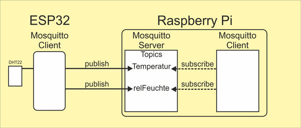
Figure 2: ESP8266 mqtt-dhtclient
For repetition:
The MQTT server is called Broker. It collects the messages from the clients on the different topics, which are Topics are called. A client can send messages on a specific topic to the broker, it is then a Publisher. If a client obtains information from the broker, then it is called a Subscriber or subscriber. It is quite possible and common for both processes to run on one client.
To quickly get to a real example, let's first use an ESP8266 as a measurement transducer that sends its results to the Mosquitto server on the Raspberry Pi, so it is a publisher.
The connection of the data line of the DHT22 is done at GPIO14 = D5. A pullup resistor of 4.7kΩ against Vcc = 3.3V must also be connected there. We take the 3.3V from pin 3V of the ESP8266. The circuit diagram clarifies the connection. The DHT22 is also available as a module with a three pin header. There the resistor is already built in. The RGB-LED in the circuit is described below.
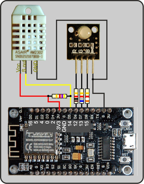
Figure 3: DHT22 client
Querying the DHT22 is a standard task for the ESP8266 because we don't even need to upload a module for it because it is already built into the core of the firmware. Exactly five commands are needed to use it. Let us start Thonny and enter the following commands via the REPL command line.
As preparation, we must import the Pin class, which lives in the module machine. Then we import the module dht and create an instance ht of the class DHT22, which is used in dht at home. ht is our sensor object.
>>> from machine import Pin
>>> import dht
>>> ht=dht.DHT22(Pin(14))
>>>
>>> ht.measure()
>>> ht.temperature()
22.1
>>> ht.humidity()
38.8
>>>
ht has the three methods measure(), temperature() and humidity(). First a measurement must be commissioned, that makes measure(). Then we only need to pick up the temperature and the rel. humidity. For a new measurement the cycle is simply repeated. After the start of the measurement the DHT22 needs a little time, which it gets automatically if we enter the commands by hand. So in a program we should allow it 100ms. Let us use a function readDHT(), which combines the previous findings and also secures the process against possible errors.
def readDHT():
    try:
        ht.measure()
        sleep(0.1)
        temp = ht.temperature()
        hum = ht.humidity()
        print("T,H",temp,hum)
        return temp, hum
    except OSError as e:
        print("Sensor error ---->",e)
        return None
If no error occurs, the try-part runs through and we get a tuple with the measured values as return. We can omit the print command later when we are satisfied that the function is working correctly. If a problem should occur that would cause the program to crash, we catch it with the except part and get the value None as feedback. You can transport the program text directly into the input window of the Thonny with Copy and Paste and accept it with "Enter". A subsequent call of the new function
>>> readDHT()
then returns output in the following form:
T,H 16.3 42.7
(16.3, 42.7)
The first line is from the print command, the second is the return value of the function. Tuples are written in round brackets in MicroPython.
Then come the status LEDs. The blue one shows us the connection to the WLAN router, the green one is the heartbeat, the sign of life of the client program and the red one informs about a malfunction. The In/Out topic also includes the function blink.
Additionally we make the flash button on the controller board usable for us. We switch pin 0 as input and activate the pullup resistor. Pressing the button connects the input to GND potential. Here I also reveal the assignment of the D-designations of the Arduino IDE on the board to the GPIO pin numbers in the MicroPython program.
statusLed=Pin(15,Pin.OUT,value=0) # blue=2
onairLed=Pin(13,Pin.OUT,value=0)  # green=1
errorLed=Pin(12,Pin.OUT,value=0)  # red=0
led=[errorLed,onairLed,statusLed ]
red,green,blue=0,1,2
taste=Pin(0,Pin.IN,Pin.PULL_UP)
# Pin translator for ESP8266 boards
# LUA pins D0 D1 D2 D3 D4 D5 D6 D7 D8
# Arduino pins D0 D1 D2 D3 D4 D5 D6 D7 D8
# ESP8266 pins 16 5 4 0 2 14 12 13 15
# SC SD
def blink(pulse,wait,col,inverted=False):
if inverted:
led[col].off()
sleep(pulse)
led[col].on()
sleep(wait)
else:
led[col].on()
sleep(pulse)
led[col].off()
sleep(wait)
These preparatory measures are best built into a program in the following, so that we can call them conveniently with a keystroke on F5. After all, there are already plenty of lines, too many to enter them again each time.
In Thonny, we open the Files menu and click on New. In the editor area, we get a new tab and below it a free work space.

Figure 4: Create new file
There we write the following lines and the two function blocks together with the definitions of the LED connections. Via Save as from the File menu we save the file in the working directory (aka workspace) under the name dhttest.py file. The folder workspace folder in the Explorer in a directory of our choice.

Figure 5: Path to the workspace directory
With F5 we can start the program now, then after a click in the terminal area we are back on the command line of REPL (Read Eval Print Loop = MicroPython shell), where we can call the functions for testing. Once we have connected the LED, we first do this with the function blink(). It takes three position parameters. The fourth one, inverted, is optional and can be set with False as default value. In this case the value set with col will turn on when the GPIO output is set to 1, i.e. 3.3V. The cathode of the LED must then be at GND potential.
col is the number of the pin object in the list led. Lists are defined in MicroPython by square brackets. So that the LEDs can also be addressed by their colors, the variables red, green and blue were assigned the numbers of the list positions. The call statusLed.value(1) has the same effect as led[blue].value(1). Objects in the list are addressed by the index, the location number, and this is also in square brackets.
Of course, for something to blink, the 3-color LED must be installed first. The connections are shown in figure 3. The assignment can also be seen in the lines that define the LED outputs.
statusLed=Pin(15,Pin.OUT,value=0) # blue=2
onairLed=Pin(13,Pin.OUT,value=0) # green=1
errorLed=Pin(12,Pin.OUT,value=0) # red=0
So, when everything is connected and the program is completely edited and saved, you are ready to go. To control your program you can use the link to my template.
F5
>>> blink(2,3,blue)
This causes the blue LED to flash for 2 seconds, then turn off for 3 seconds. You will not notice anything of the 3 seconds except the program delay. The REPL prompt ">>> " appears after the LED goes off, but only after three seconds. During the light and dark phase nothing happens, no command can be executed when the ESP8266 is sleeping, which we can do with the command sleep() command. In uncritical situations such delays can be well built into the program without side effects.
The program text up to here is under dhttest.py for download.
But if other things have to be done during the waiting time, then a different approach is called for. This brings us to the next function, TimeOut().
def TimeOut(t):
    start=ticks_ms()
    def compare():
        return int(ticks_ms()-start) >= t
    return compare
TimeOut() takes a time duration in milliseconds and returns the reference to a function which, after the time period has expired, returns the value True after expiration. This tricky construct has the name Closure. About how to deal with it, you can read in this PDF document for more detailed information. Now let's add the function text to our program. We also need to add the function ticks_ms() from the module time module. To do this, we extend the corresponding import line with this function name. Then we move on to the next test.
from time import sleep, ticks_ms
Function text enter or copy
Save,
F5 and then
>>> expired=TimeOut(10000)
>>> expired()
False
>>> expired()
False
>>> expired()
True
The REPL prompt now comes back immediately after the call, and we can send the subsequent function calls. How does this work?
The name expired is assigned by calling TimeOut(10000) the reference to the function compare() function, which is passed within TimeOut() has been defined. This function compare accesses the parameter t which we use when calling TimeOut(). It is thanks to the special structure of this construct that compare() to the contents of t even if the function TimeOut function has already been exited. Normally, all objects that were defined within a function, i.e. locally, are destroyed when the function is exited.
So we are able to program delays during which any other things can be executed. This is important for our MQTT project. With the one function TimeOut() any number of different timeouts can be programmed, which can be queried at any point in the program, as long as they are in the respective namespace.
The network connection for MQTT
For MQTT we need a network access for our ESP8266. This is built in the next section of the program, after we have ordered an evil genie into the bottle. The firmware of the ESP8266 releases a genie without our intervention and knowledge, which can cause days of troubleshooting. As soon as a WLAN connection to a router is established, the genie wakes up and drives you to despair, because the ESP8266 constantly reboots. This is due to two things.
The first evil is webrepl, the radio command line that can be operated via a browser, similar to REPL via the USB cable. Flashing the firmware puts the part on hold. Turning it off goes like this. We import webrepl_setup and enter a D at the prompt. After that we restart the ESP8266 (RST). This operation has to be done only once after every new flashing of the ESP8266 with the firmware must be performed.
>>> import webrepl_setup
> D
Perform reset
The second evil is that the AP interface is automatically activated. This is bullshit, because it is up to the programmer which interface he wants to use. In addition, the error is nowhere documented on the web. So one searches for a wolf. On a Amica I came across this circumstance as the cause of the error. The board is a bigger chatterbox than the ESP8266-NodeMCU. So the AP interface must definitely be switched off, then everything runs quite tamely as desired. The following sequence must be in the program, before our actual STATION interface is initiated. MicroPython does not support parallel operation of the two interfaces, this is the background of the problem.
nac=network.WLAN(network.AP_IF)
nac.active(False)
nac=None
These lines must start with with every restart of the controller and therefore belong in a program that uses the station interface.
But now to the setup of the WLAN connection. First of all, one line must be added to the imports.
import network
The module provides us with various constants and with the method WLAN(), with which we can call the network interface object nic in station mode.
When typing or copying the text into your program, please remember to use your own access data for the WLAN router. The function hexMAC() creates from the bytes object byteMac a reasonably readable string of the MAC address of the active interface. byteMac[i] returns the i-th character, hex() turns it into a string of the form 0xAB and we are interested in the characters from the 2nd position on. Separator is a "-".
def hexMac(byteMac):
"""
The hexMAC function takes the MAC address in bytecode
and forms a string from it for the return
"""
macString =""
for i in range(0,len(byteMac)):
macString += hex(byteMac[i])[2:]
if i <len(byteMac)-1 :
macString +="-"
return macString
# ***************** Connect to WLAN **********************
connectStatus = {
0: "STAT_IDLE",
1: "STAT_CONNECTING",
5: "STAT_GOT_IP",
2: "STAT_WRONG_PASSWORD",
3: "NO AP FOUND",
4: "STAT_CONNECT_FAIL",
}
myMQTTserver = "10.0.1.99"
#mySSID = 'Here_goes_your_SSID'
#myPass = 'Here_goes_your_Password'
# Be sure to turn off the AP interface
nac=network.WLAN(network.AP_IF)
nac.active(False)
nac=None
# We create a network STATION instance
nic = network.WLAN(network.STA_IF)
nic.active(False)
# Request the MAC address to be entered in the router,
# so that the release of the access can take place
MAC = nic.config('mac')
myID=hexMac(MAC)
print("Client ID",myID)
The Dict connectStatus returns the plain text message whose number the command nic.status() returns.
This is followed by switching off the AP mode as described above. The STATION interface is also initially deactivated after instantiation. Then we display the MAC address of the interface. For single-digit values, a leading 0 is added.
The MAC address (Media Access Control) is a unique identifier of each network interface. The combination of six two-digit hexadecimal values must usually be stored with the router so that it allows the network device access. It is also possible to set the router to allow all new devices. However, this is security hara-kiri and not recommended. The last three lines provide us with the usual notation of the MAC address of the station interface.
We let the program run until here and then enter the displayed MAC at the router. Where and how this has to be done depends on the device. Please consult your router manual.
Read the complete text of the previous program can be downloaded here.
The next steps are to activate the station interface, assign an IP address, and log on to the WLAN access point. Specifying a static IP address will disable the DHCP client of the ESP8266, which would try to obtain an IP from a DHCP server. This usually runs on the WLAN router or on another server in the house. The order of the dotted-quads is: IP address, network mask, gateway=router IP, DNS server.
# We activate the network interface
nic.active(True)
# Establish the connection
# We set a static IP address
nic.ifconfig(("10.0.1.98","255.255.255.0","10.0.1.25",\
"10.0.1.25"))
# Log on to the WLAN router
nic.connect(mySSID, myPass)
The ESP8266 is now waiting for the release from the WLAN router. In the while loop the connection status is retrieved. As long as isconnected() is not True we remain in the loop. a dot followed by the status code is output. However, because no PC is connected during use - the system is supposed to run autonomously - the blue LED shows us by a long glow and a short pause that the connection is not yet established. If everything has worked, then we get the corresponding messages in the terminal area. These last print lines can also be deleted without damage in the production system.
if not nic.isconnected():
# wait until the connection to the access point is established
while not nic.isconnected():
print("{}.".format(nic.status()),end='')
blink(0.8,0.2,blue) # blink blue LED long-short
# When connected, show connection status & config data
print("\nconnected: ",nic.isconnected())
print("\nConnection status: ",connectStatus[nic.status()])
# Was the configuration successful? Control
STAconf = nic.ifconfig()
print("STA-IP:\t\t",STAconf[0],"\nSTA-NETMASK:\t",\
STAconf[1],"\nSTA-GATEWAY:\t",STAconf[2] ,sep='')
For comparison here is again a Download of the program up to this point. A start with F5 should give the following result.
>>> %Run -c $EDITOR_CONTENT
Client-ID 10-52-1c-2-50-24
#7 ets_task(4020ee60, 28, 3fff92d0, 10)
1.1.1.
connected: True
Connection status: STAT_GOT_IP
STA-IP: 10.0.1.98
STA-NETMASK: 255.255.255.0
STA-GATEWAY: 10.0.1.25
>>>
A ping from the Raspi or another computer in the same subnet should now also be positive.

Figure 6: Ping response from DHT22 client
Last but not least - the MQTT section
The connection to the MQTT server is established by a function that refers to the module umqttsimple.py module. Consequently, this module must be uploaded to the ESP8266 so that we can use the class MQTTClient can be imported from it. We add this line and one more little thing in the import section. It now looks like this.
from machine import Pin, reset
from time import sleep, ticks_ms
import dht
import network
from umqttsimple import MQTTClient
import esp
esp.osdebug(None)
import gc
gc.collect()
First we deal with the task of sending measured values to the broker. So this part of the program works as a publisher. For this we need two functions and a few variables.
As a supplement to the functioning of a broker, we take a look at the hierarchy of the namespace of the topics. Similar to directories on a PC, there are different levels separated by a slash "/". In addition to basic topics such as attic, garden and apartment, we want to use here the topic basement we want to address. There is the storage cellar, from which we are interested in the temperature and the relative humidity. We also want to control a fan motor there. In the heating system, we will later be interested in the flow and return temperature. In addition, we would like to be able to remotely control the circulation pump and the burner of the heating system. But for the time being, let's stay with the topics, which we define by the following variables.
nextMsgDelay=5000 # Measurement interval in ms
topicTemp="basement/temperature"
topicHum="cellar/humidity"
topicAirflow="basement/ventilator"
topicDone="basement/fan/done"
When switching a relay, we have to take into account on the ESP8266 NodeMCU V3, which is in use here, that on pin Vin an external 5V voltage source can be connected, but that on the other hand there are not the 5V of the USB port is available. Therefore, for the operation of a relay module an external 5V source is necessary even during development. Later we need it for autonomous operation anyway. As a simpler solution, we connect any LED with series resistor against Vcc=3.3V to the control output D1 = GPIO5 during the development phase. The LED is then switched on by 0V at output D1, just like the LOW level triggered relay.

Figure 7: DHT22 client with LED at the switching output
The function connect2Broker() tries to connect to the Mosquitto server. If this fails, an exception is thrown, which we have to catch in the main program. More about this later.
def connect2Broker():
    global myID, myMQTTserver
    # Create client instance
    client = MQTTClient(myID, myMQTTserver)
    client.connect()
    print("Connected to "+myMQTTserver)
    return client
Calling the constructor of the class MQTTClient returns a client instance which establishes the connection to the broker. A reference to this object is returned to the calling program.
If the connection cannot be established, then the ESP8266 is restarted after the time in seconds specified with sleep() has elapsed.
def restartClient():
    print("connection to {} failed - Rebooting".\
           format(myMQTTserver))
    sleep(10)
    reset()
Before entering the service loop, we try to connect to mosquitto. If the attempt fails, the except part will restart the system.
try:
client = connect2Broker()
except OSError as e:
restartClient()
sendNow=TimeOut(nextMsgDelay)
sendNow() is the timer function to which the function TimeOut() returns a reference to. After the interval, whose duration we specify in the parameter nextMsgDelay parameter, returns sendNow() returns the value True back. Now it goes into the main loop.
while True:
    try:
        if sendNow():
            resp=readDHT()
            if resp is not None:
                temp, hum = resp
                temp = (b'{0:3.1f}'.format(temp))
                hum =  (b'{0:3.1f}'.format(hum))
                client.publish(topicTemp, temp)
                client.publish(topicHum, hum)
                blink(0.1,0.05,green)
                sendNow=TimeOut(nextMsgDelay)
            else:
                print("Sensor error!")
                blink(0.2,0.3,red)
                blink(0.2,0.3,red)
                blink(0.2,0.3,red)
    except OSError as e:
        restartClient()
As a precaution we save again with try - except. In case of a (still) unknown error we would restart.
If sendNow() returns True, it is time to take a new measurement and send the values. Because it may be that for some reason readDHT() returns the value None (sensor error), we first read the return into a variable, which we subsequently check. Only if values were really delivered, we unpack them into the variables temp and hum. After the conversion to strings we publish the values under the corresponding topic. Let the heartbeat LED blink briefly and reset the timer. Done! The whole program dhttest_mit_MQTT.py can be downloaded here here.
You think, now it's time for a first test. Agreed, here we go! Let's open a terminal on the Raspi or on the PC via Putty. There we enter the following line.
mosquitto_sub -t "basement/temperature" -t "humidity"
Then we start our program on the ESP8266 - F5. After 5 seconds, we see the first two measured values in the terminal window and on the Python shell in Thonny - after 5 seconds, the next ... In both cases, we can cancel with Ctrl + C.
But - something is still missing. We wanted to switch a fan motor. OK, we don't have a motor at hand at the moment, for testing an LED is enough. The wiring is shown in Figure 7. For the production system we can replace the LED with one of the relays from the dual module.
I do not want to omit a hint for the selection of this duo module at this point. The air gap between the low voltage side of the module and the medium voltage side (230V) gives us more dielectric strength. There are two single versions. One also brings the protection through the air gap, but has no mounting holes. A second one has no air gap although the switching contact of the relay and the input contacts of the low voltage side have only a distance of about 2mm.
In any case, there is a danger to life when experimenting with mains voltage at the contact. Please keep this in mind when experimenting with voltages greater than 50V.
Let's go to the last round. To receive messages from the broker we have to
- specify a topic we want to subscribe to
- provide a function that assigns incoming messages to a specific action based on the topic
- make this function known to the MQTTClient class
- subscribe to the desired topic
- listen for incoming messages from the broker
- publish the success of the action
Ad 1. and 6.
We have already done this above when we set the variable topicAirflow variable. At this point we add another topic, through which we can publish a feedback to the brocker
topicAirflow="basement/fan"
topicDone="basement/fan/done"
In the variable declarations section we add the definition of the pin for the switching output.
relay=Pin(5,Pin.OUT,value=1)
Ad 2. and 6.
def messageArrived(topic,msg):
    topic=topic.decode()
    msg=msg.decode()
    print("Topic:",topic," message:",msg)
    if topic == topicAirflow:
        if msg=="an":
            relay.value(0)
            client.publish(topicDone, "AN")
        else:
            relay.value(1)
            client.publish(topicDone, "OFF")
This function converts the received bytes objects into strings, compares if the topic is correct and executes what there is to do if necessary. Here the output is switched to the relay. After the switching process, the feedback is sent to the broker, whose topic can be subscribed to by the client.
Ad 3. and 4.
def connect2Broker():
    # create client instance
    client = MQTTClient(myID, myMQTTserver)
    client.set_callback(messageArrived)  # (A)
    client.connect()
    client.subscribe(topicAirflow)       # (B)
    print("Connected to:", myMQTTserver)
    print("Subscribed to:",topicAirflow)
    return client
The function connect2Broker() receives 2 essential lines of growth.
(A) We tell the client object which function to execute when a response arrives from the broker. For this we pass a reference to the function messageArrived.
(B) We subscribe to the topic specified in the variable topicAirflow variable.
Ad 5.
In the while loop we add the eavesdropping command for subscribed topics. It passes the execution to the function messageArrived() if a new message has arrived.
while True:
    try:
        client.check_msg()
        if sendNow():
Also for this there is again the completely supplemented program dhtclient.py for download.
For testing we open another terminal on the Raspi. From there we send the following messages.
mosquitto_pub -t "basement/fan" -m "an"
mosquitto_pub -t "basement/fan" -m "off"
Have you observed the LED on the ESP8266? On - off. In addition, the following lines were output in the Thonny terminal.
Topic: cellar/fan    Message: to
Topic: cellar/fan    Message: from
In a second terminal we can also test the feedback to the broker.
mosquitto_sub -t "basement/fan/done"
Reply:
AN
OFF
…
This brings us to the end of this blog post. The next episode will be about outputting the data that the broker collects from the various measurement stations to a control unit on an LCD display. We will use the buttons on the LCD keypad to send commands to the measurement stations. We will again see the feedback on the display. The control will be done by an ESP32.
But wait, there was talk about another ESP8266. What should happen with it?
Well, the other ESP8266 should monitor the heating, supply and return temperature. By the way, the circulating pump should be switched and why not the whole system as well? For this two sealed DS18B20 sensors are intended and for each switching operation a relay of a two stage. The programming is not much different from today's program except for the sensors. Interrogating the DS18B20 is as simple as with the DHT22. If you need help, you will find it in advance in the article about the Frost monitor in the greenhouse.
In the software chapter Autostart describes how to start the program as boot.py to the ESP8266 to let it boot autonomously. These two points I leave to you today as homework.
Next time we will put ESP8266 and ESP32, together with the display, into service as an autonomous control and monitoring unit.
PDF version of this episode can be downloaded here: esp_mqtt-client1_ger.pdf.


6 comments
Bernd-Steffen Großmann
Nachtrag zu meinem letzten Kommentar: Auch mit einem größeren Widerstand (22 kOhm) funktioniert es nicht, das Relais fällt nicht mehr ab. Bei Widerständen >= 47kOhm schaltet es gar nicht mehr. :(
Hab es jetzt, wie im Datenblatt des KF-301 (1-Relais 5V Modul Low-Level-Trigger) in der Schaltung mit dem Raspi angegeben, mit 3,3V-Versorgungsspannung betrieben und so funktioniert es jetzt. Ganz versteh ich es nicht, warum die Ansteuerung bei 5V Versorgung nicht funktioniert, aber was solls?
Mit freundlichen Grüßen,
Bernd-Steffen Großmann
Bernd-Steffen Großmann
Hallo Herr Grzesina, ich bin jetzt ein ganzes Stück weitergekommen. Die Temperatur- und Luftfeuchte-Erfassung funktioniert (keine Ahnung, warum die Funktion “ht.measure()” auf Fehler lief) und auch die Übertragung per MQTT an NodeRed auf dem Raspi klappt. ;0) Auch die manuelle Schaltung des Relais (simuliert mit LED) per Befehl (mosquitto_pub t “keller/ventilator” -m “an” bzw. “aus”) geht. Als ich allerdings ein 5V-Relais (von AZ-Delivery) in die Schaltung einbaute, reichten die 3,3 V am GPIO-4-Ausgang des ESP8266 nicht aus, das Relais (Eingang low-aktiv) zu schalten bzw. es wurde dauerhaft eingeschaltet. Meine Annahme, dass die 3,3V am low-aktiven Eingang des Relais-Bausteins bereits als Low angesehen werden, wurde wohl bestätigt, denn: als ich einen 10 kOhm Widerstand in Reihe zwischen GPIO und Eingang setzte, wurde der Baustein nun ein und ausgeschaltet. Allerdings fällt das Relais nicht mehr ab, obwohl die Signal-LED am Relais ausgeht!? Der Arbeitsstrom-Kontakt (NO) ist weiter geschlossen. Ich werde wohl den Widerstand noch erhöhen müssen.
Mit freundlichen Grüßen,
Bernd-Steffen Großmann
Bernd-Steffen Großmann
Noch eine Ergänzung zu meinem vorigen post:
Die Funktionen ht.temperature() und ht.humidity() funktionieren dann aber fehlerfrei!?
Ebenso der Funktionsaufruf readDHT()…
Mit freundlichen Grüßen,
Bernd-Steffen Großmann
Bernd-Steffen Großmann
Hallo herr Grzesina, danke für die Links. Da konnte ich mir schon mal einige Beispiele anschauen und mit dem ESP8266-Aufbau testen. Jetzt hab ich auch eine Schaltung mit AM2302 (DHT22) aufgebaut (lediglich statt des 4,7 k pullup-Widerstands 10 k), aber ich bekomme gleich bei Test – nach Eingabe von “ht.measure()” folgende Fehlermeldung:
Traceback (most recent call last):
File “”, line 1, in
File “dht.py”, line 23, in measure
OSError: [Errno 110] ETIMEDOUT
Den Sensor hab ich in der Schaltung noch separat mit einer ESP32-MCU mit Arduino-DTH22-Test-Sketch geprüft. Der ist in Ordnung. Wo kann der Fehler liegen?
Mit freundlichen Grüßen,
Bernd-Steffen Großmann
Jürgen
Hallo, Herr Großmann,
eine Liste mit allen meiner bereits veröffentlichten Micropython-Projekte finden Sie unter
http://grzesina.de/az/mcp-projekte.html
Darin gibt es auch eine Liste mit den Links zu den Modulen, die in den Projekten eingesetzt wurden.
http://grzesina.de/az/mcp-projekte.html#_Toc97282554
Viel Vergnügen beim Erforschen!
Grüße
Jürgen
Bernd-Steffen Großmann
Hallo herr Grzesina, das ist ja eine sehr interessante Serie über MikroPython, NodeRed etc.! Ich habe gerade Thonny auf meinem PC installiert und auf einen ESP8266 die neueste MikroPython Version 1.18 geflasht. So weit so gut. Den ersten Befehl print(“Hello world!”) habe ich auch erfolgreich auf dem ESP ausführen können. Wobei ich jetzt scheitere, ist das Auffinden der py-Dateien (button.py, keepad.py, lcd.py …) in Ihrer Thonny-Dokumentation (http://grzesina.de/az/die_entwicklungsumgebung_thonny.html). Die sind zwar für diesen Beitrag nicht notwendig, aber zum Test würde ich die schon gern mal ausprobieren. Wo finde ich diese Dateien? Mit freundlichen Grüßen,
Bernd-Steffen Großmann