
This and subsequent posts will present experiments that can be performed using only the components included in the kit. The series of articles will be structured systematically so that it provides an introduction to using a microcontroller. Apart from the use of a computer, no previous knowledge is required.

The software examples are kept simple and are intentionally not offered for download, since you learn more when you type the code yourself.
Required hardware
|
Number |
Component |
Note |
|
1 |
|
|
|
1 |
9 V block battery or 9 V power supply unit |
optional |
Microcontroller
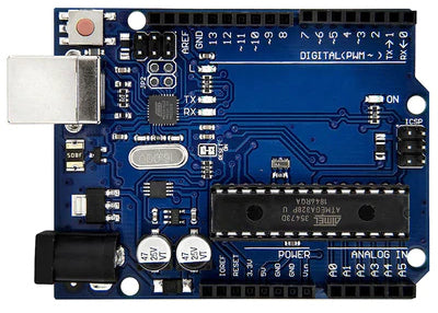
The core of the set is the board with the ATMEGA 328 P microcontroller. This microcontroller corresponds to a complete computer system with CPU, 32 k byte program memory, 2 k byte data memory and twenty input/output ports. The 328P can be programmed via a serial interface. The IO pin 0 is used as input (RX) and the IO pin1 as output (TX).
On the so-called breakout board included in the set, all inputs/outputs are led out on female connectors. Via a second small microcontroller a gateway between USB bus and serial interface is realized. This way a communication between computer and microcontroller can be established. Furthermore there is a crystal for the clock generation and voltage regulators for the power supply.
There are two ways to supply the board with power. The easiest is via the USB connector. Alternatively there is a socket for an external power supply. Here voltages between 7 V and 12 V can be used. Typically, 9 V is mostly used. The power supply input is also protected against incorrect polarity by a diode.
Development environment
To create a program for the microcontroller, you need different software tools. If you do not want to create the program directly in the machine code of the ATMEGA, you need a compiler for the desired programming language. You also need a program to transfer the compiled code to the microcontroller and write it into the program memory there. It is practical if a tool combines all these functions. This is then called an integrated development environment (IDE). The free open source software Arduino IDE is such a program. The processor ATMEGA 328P is directly supported. The programming language used is C or simplified object-oriented C++. But don't worry, if you don't want to go in depth, you can learn the basics easily and quickly. The IDE does most of it automatically in the background, so you can concentrate on the actual program. The software can be run directly on https://www.arduino.cc/en/software download.
When the IDE is started after installation, the following picture appears.

An empty program, here called Sketch, is automatically created. The name of the sketch is generated from the current date. The name can be changed as desired via "File->Save as". The default sketch contains two functions that must always be present. The function setup() is called once when the microcontroller is started, the function loop() again and again in an endless loop.
If the microcontroller is now connected to the computer via the USB cable, the USB driver that was installed with the Arduino installation should be activated. In the menu item "Tools" of the IDE now in the item Port "COM# (Arduino Uno)" should appear, where # stands for a port number that may be different on each computer. This port should be selected. Under the item "Board" should appear "Arduino Uno" should appear.
After this preparation nothing stands in the way of a first sketch. The word "Hello" is to be output via the serial interface. For this purpose two functions have to be inserted into the setup() function.
void setup() {
// put your setup code here, to run once:
Serial.begin(9600);
Serial.println("Hello!");
}
The command Serial.begin(9600); initializes the serial port with a speed of 9600 baud (bits/s). With the second command Serial.println("Hello!"); prints the word "Hello" and a line feed. If instead of println only print the output is done without a line feed. In C/C++ all command lines must be terminated with a semicolon.
In order to display the output, the item "Serial Monitor" must be selected in the menu item "Tools". An extra window opens for the display. In the footer "9600 Baud" should be displayed as speed.

If you now click on the arrow in the upper left corner of the IDE, the sketch will be compiled and transferred to the microcontroller. After the transfer a reset is triggered at the controller and thus the program is started. The word "Hello" should appear in the serial monitor.
Digital outputs
All 20 inputs/outputs can be used as digital outputs. For a port to be used as an output, it must be configured with the command pinMode(13,OUTPUT); (here pin 13) to define it as an output. The output can take two values. With the command digitalWrite(3,1); the value 1 is output to pin 13, i.e. the pin goes to 5V. With the command digitalWrite(3,0); the value 0 is output to connection 13, i.e. the pin goes to 0V.
On the board there is a yellow light emitting diode connected to pin 13. With a simple sketch it should be made to blink. For the sketch the command delay(1000); is needed. This command delays the program execution by the specified number in milliseconds. In the setup function pin 13 is defined as output. This time the loop function is also used to switch the LED on and off.
void setup() {
// put your setup code here, to run once:
Serial.begin(9600);
Serial.println("Start");
pinMode(13,OUTPUT);
}
void loop() {
// put your main code here, to run repeatedly:
digitalWrite(13,1);
delay(1000);
digitalWrite(13,0);
delay(1000);
}
Diode and light emitting diode LED
A diode, or rectifier, is a device that allows current to flow in only one direction. If a positive voltage is applied to the anode with respect to the cathode, a current can flow. However, the current flow does not start immediately, but only when the so-called threshold voltage is reached. For silicon diodes, the threshold voltage is about 0.7 volts. When the polarity is reversed, no current flows until the breakdown voltage is reached. The breakdown voltage can be very high for diodes. Two diodes of type 1N4007 are included in the set. The threshold voltage is 0.6 V, the breakdown voltage 1000 V and current carrying capacity 1 A.
The figure shows the circuit symbol and a photo of the diode. The ring on the right indicates the cathode
A light emitting diode behaves like a simple diode. By using special semiconductor materials, light waves are emitted above the threshold voltage when current flows. The threshold voltage is much higher and depends on the achieved luminous color. The longer connecting wire indicates the anode. The set includes five LEDs each in the colors red, yellow, green, blue and white.

|
|
red |
yellow |
green |
blue |
white |
|
Threshold voltage |
1.89 V |
1.99 V |
2.54 V |
2.75 V |
2.77 V |
In order for a light emitting diode to be operated from a voltage source, a series resistor is required to limit the current. The current also determines the brightness. With a series resistor of 1000 Ohm you get for a red light emitting diode:
(Uout - USwell) / Rv = (5 V - 1.89 V) / 1000 Ohm = 3.11 mA
This current gives sufficient brightness and does not overload the output of the microcontroller.

Sketch traffic light
As an application example, the microcontroller is to simulate a traffic light with LEDs. The signal sequence shall be:
Red -> Red/Yellow -> Green -> Yellow -> Red -> Red/Yellow -> ......
Two groups of three LEDs are to be used for both directions of travel. The circuit looks like this and can be built on the small plug-in board. The LEDs are connected to the digital outputs 2 to 7. Each LED gets a series resistor with 1 kOhm. The cathodes of all LEDs are connected to GND.


The sketch contains some new commands. With #define name constant you can assign a name to a constant. This makes the program more readable and if such a constant is used several times, its value can be easily changed in one place. The compiler replaces the names with the corresponding constants before compiling.
To store the state of all six LEDs in one byte, one bit is assigned to each LED. If you put 0B in front of the constant, it can be entered in binary.
#define GRUEN1 0B000001
#define YELLOW1 0B000010
#define RED1 0B00000100
#define GREEN2 0B00001000
#define YELLOW2 0B00010000
#define RED2 0B00100000
Also the numbers of the used pins are defined like this
#define PIN_GRUEN1 2
#define PIN_YELLOW1 3
#define PIN_ROT1 4
#define PIN_GRUEN2 5
#define PIN_YELLOW2 6
#define PIN_ROT2 7
The number of steps indicates after how many steps the pattern repeats.
#define MAX_steps 4
Now follows the definition of the global variables. These are memory locations in RAM that can be accessed as long as the controller is powered. Global means that these variables can be accessed from anywhere. Two lists of values are needed to store the signal sequence. A list of values is defined by first specifying the data type. This is followed by the name for the variable and in square brackets the number of elements. Now the variable is declared. You can also assign values to it. The assignment is introduced with an equal sign. After that, the individual values follow in curved brackets separated by commas.
The first list with the name signals defines the patterns by setting the bits for the LEDs that should light.
The second list with names times contains the duration for the individual steps in seconds. Here the data type int is used for values between -32767 and +32767.
The following is a simple variable of type bytewhich is eight bits and always stores the current step.
byte signale[MAX_SCHRITTE] = {
GREEN1 + RED2,
YELLOW1 + RED2 + YELLOW2,
RED1 + GREEN2,
RED1 + YELLOW1 + YELLOW2
};
int times[MAX_steps] = {6,2,10,2};
byte step = 0;
In the setup function, as in the first example, the serial interface is initialized and a text is output. Then the pins for the LEDs are defined as output and finally the Current Step is set to 0.
void setup() {
// put your setup code here, to run once:
Serial.begin(9600);
Serial.println("Start traffic light");
pinMode(PIN_GRUEN1,OUTPUT);
pinMode(PIN_YELLOW1,OUTPUT);
pinMode(PIN_ROT1,OUTPUT);
pinMode(PIN_GRUEN2,OUTPUT);
pinMode(PIN_YELLOW2,OUTPUT);
pinMode(PIN_ROT2,OUTPUT);
step = 0;
}
In the function loop the LEDs are switched. First a local variable v is defined to store the pattern for the current step. Local means that only within this
function can access this variable. Whether an LED should light up or not can be found out by filtering out the corresponding bit. The logical AND operation is suitable for filtering.
Example: The second step has the pattern YELLOW1 + RED2 + YELLOW2 or binary 00110010. An AND operation with GREEN1 = 00000001 returns 0000000, because the corresponding bit is not set. An AND operation with YELLOW1 = 00000010 returns 00000010 or decimal 2.
The result of the AND operation can be checked with the function digitalWrite(Pin,Value); directly to the pin. IIf the value is 0, the pin goes to 0 V and if the value is not 0, the pin goes to 5 V and the LED lights up.
After all pins have been set according to the pattern, the current values are output to the serial interface for checking. Then the program waits as long as in the list times list. Since the values in the list times are seconds, they must be multiplied by 1000 because the function delay() expects milliseconds. Last but not least, the pedometer is started with the command step++ increases it by one. If the maximum number of steps is reached, the step counter must be set to 0 again.
void loop() {
byte v = signale[step];
digitalWrite(PIN_GRUEN1, v & GRUEN1);
digitalWrite(PIN_YELLOW1, v & YELLOW1);
digitalWrite(PIN_ROT1, v & RED1);
digitalWrite(PIN_GRUEN2, v & GRUEN2);
digitalWrite(PIN_YELLOW2, v & YELLOW2);
digitalWrite(PIN_ROT2, v & RED2);
Serial.print("Step = ");
Serial.print(step);
Serial.print(" Duration = ");
Serial.print(times[step]);
Serial.println(" s");
delay(times[step]);
step++;
if (step == MAX_SCHRITTE) step = 0;
}
Relay
A relay is a mechanical switch controlled by an electromagnet. When current flows through the coil of the electromagnet, an iron armature is attracted, which switches the switch contact. The illustration shows the structure, the switch symbol and a picture of the relay from below and above.

The advantage of a relay is the galvanic isolation between control circuit and load circuit. Thus, large voltages and currents can be switched with it by a microcontroller. Furthermore, it does not matter whether direct or alternating current is to be switched. The relay in the starter kit is controlled with 5 V. In the active state, it requires a current of 70 mA. The switching contacts can switch currents up to 10 A at DC voltages up to 30 V or AC voltages up to 250 V. The isolation between the control circuit and the load circuit can withstand a voltage of 1500 V.
Transistor
A transistor is an electronic component that allows large output currents to be controlled with small input currents. The ratio of output current to input current is called current gain. For the two transistors in the starter kit, the current gain is 300. The transistor has three terminals. The emitter is common for input and output. The base represents the input and behaves like a diode. If the threshold voltage of 0.7 V is exceeded, an input current flows which is to be limited by a series resistor. This input current causes a proportional output current to flow across the path between the collector, which represents the output, and the emitter, depending on the input current. This continues until the voltage between the collector and the emitter is only about 1V. This state is called saturation.
Since the relay needs a current of 70 mA to operate, it cannot be controlled directly by the microcontroller. Here the transistor can be used. For an output current of 70 mA, an input current of 70 / 300 = 0.23 mA is needed. The microcontroller supplies a voltage of 5 V at the output. Subtracting the threshold voltage of 0.7 V, there is then 4.3 V at the series resistor. This results in 4.3 V / 0.23 mA = 18.4 kOhm for the series resistor. In the starter kit there are resistors with 10 kOhm. With the 10 kOhm resistor, the input current is 0.43 mA. This means that the relay will surely get enough current for safe switching.
Since the solenoid is an inductor, it will try to maintain current when switched off. Since this is not possible due to the broken circuit, a high voltage spike occurs across the coil which would destroy the transistor. Therefore, a diode is connected in parallel with the coil, which allows the coil to allow the current to decay. This avoids the voltage spikes. The figure shows the circuit symbol for a transistor, a picture of the transistor from the starter kit and the finished control circuit for a relay.
![]()
The two transistors in the starter kit are of type PN2222A and have the following characteristics:
Current gain 300,
Base threshold voltage 0.66 V,
collector - emitter reverse voltage maximum 30 V,
collector current maximum 600 mA
The input can be connected to a pin of the microcontroller. The control is done as for the light emitting diode with the command digitalWrite(pin, value).


4 comments
Jens Schiel
Warum ist das ganze nicht so direkt in der Box oder dem Buch welches dabei ist?
Ich habe da leider googeln müssen bzw YouTube fragen was ich damit überhaupt machen kann und wie da manche Dinge funktionieren. Das ist leider nicht so gut für Anfänger finde ich leider 😔
Da steht zb nirgends wie ein Breadboard funktioniert oder ähnliches
Andreas Wolter
@Klaus: wie Gerald Lechner in seinem Beitrag erwähnte, soll für den Lernprozess nicht einfach der Code heruntergeladen werden. Copy&Paste geht natürlich trotzdem.
Ich habe alle blauen Codeelemente testweise in einen Sketch kopiert. Er ließ sich problemlos kompilieren.
Mir ist dabei aufgefallen, dass die Zeile #define MAX_SCHRITTE 4 nicht blau markiert war. das habe ich behoben. Die gehört dazu.
Also alle #define Zeilen
Dann die Funktion signale() auch mit den darunter eingefügten globalen Variablen.
dann die loop() und zum Schluss die setup() Funktion.
Es ist nicht durcheinandergewürfelt, daher sollte gar nicht viel zu puzzlen sein.
Grüße,
Andreas Wolter
AZ-Delivery Blog
Klaus
ich habe versucht den Sketch der Verkehrsampel zusammenzupuzzeln und zu kompilieren – leider ist aus dem Text nicht klar ersichtlich, in welchen Teil die verschiedenen Programmteile gehören.
Könnt ihr bitte den Sketch noch mal komplett darstellen – bzw. als download anbieden ? Danke !
Jean paul LESTIENNES
Pouvez vous traduire les texte