
This blog sequence is also available as PDF document.
Solar cells, if we disregard procurement and installation costs, provide free and environmentally friendly electrical energy. This is nothing new. Of course, the operation should be as effective as possible. That's why today we're going in search of the MPP, the maximum power point, i.e. the operating state in which the panel emits the greatest possible energy. Temperature, irradiance and load of the module have an influence on the position of the MPP.
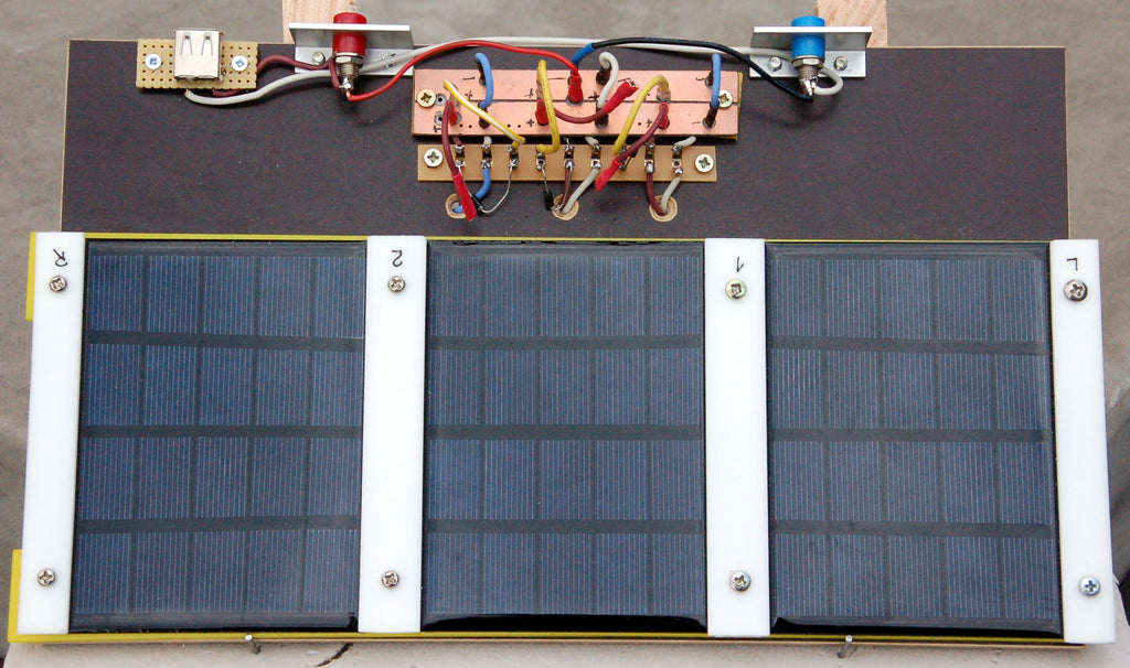
Image 1: Mounted solar panels
An ESP32 and a buck converter with a MOSFET power transistor help us find it. How this works in detail I will tell you in today's episode of
MicroPython on the ESP32 and ESP8266
today
The ESP32 in search of the MPP
The point is to find out at which panel voltage the MPP is reached. The panel voltage in turn depends on the load of the module at a given irradiance and module temperature. This has to be changed, or better let the ESP32 change it. The buck converter from the first episode of the solar series will serve together with a load resistor as variable load and an INA219 as measuring servant, whose function I will describe in the second sequence in the second episode. There will be a lot of measured values, so many that it would be annoying to record and evaluate everything by hand. Therefore the values have to be beamed to the PC. One method uses the USB port, another uses the radio property of the ESP32. And this is what the result looks like when the series of measurements is displayed graphically with the help of a calculation program. I used Libre-Office for this.

Image 2: Evaluation of a measurement series with Libre Office
Hardware
The hardware list from the first episode was supplemented by the solar panels and a 4.7Ω /2W resistor.
|
1 |
|
|
1 |
|
|
1 - 3 |
Solar Panel 5V 1.5W Waterproof Polysilicon Mini Solar Module |
|
1 |
INA219 |
|
1 |
N-channel MOSFET IRLZ24 (logic level gate, R on = 60mΩ) |
|
1 |
Transistor BC337 |
|
2 |
Resistor 270 Ω |
|
2 |
Resistor 150 Ω |
|
1 |
Resistance 10 kΩ |
|
1 - 3 |
Schottky diode 1N5817 |
|
1 |
Electrolytic capacitor 470µF 16V |
|
1 |
Electrolytic capacitor 220µF 16V |
|
1 |
Storage choke 330µH 1A |
|
1 |
Resistor 4.7 Ω / 2W |
|
various |
|
|
1 |
|
|
4 |
Soldering board with 6 contacts each or |
|
1 |
Base board 16cm x 24cm |
The software
For flashing and programming the ESP32:
Thonny or
Used firmware for the ESP8266/ESP32:
The MicroPython programs for the project:
ssd1306.py Hardware driver to the OLED display
oled.py API for the OLED display
ina219.py Driver module for the INA219
powerline.py Program to find the MPP
MicroPython - Language - Modules and programs
For the installation of Thonny you find here a detailed manual (english version). In it there is also a description how the Micropython firmware (as of 02/05/2022) on the ESP chip. burned is burned.
MicroPython is an interpreter language. The main difference to the Arduino IDE, where you always and only flash whole programs, is that you only need to flash the MicroPython firmware once at the beginning to the ESP32, so that the controller understands MicroPython instructions. You can use Thonny, µPyCraft or esptool.py to do this. For Thonny, I have described the process here described here.
Once the firmware is flashed, you can casually talk to your controller one-on-one, test individual commands, and immediately see the response without having to compile and transfer an entire program first. In fact, that's what bothers me about the Arduino IDE. You simply save an enormous amount of time if you can do simple tests of the syntax and the hardware up to trying out and refining functions and whole program parts via the command line in advance before you knit a program out of it. For this purpose I also like to create small test programs from time to time. As a kind of macro they summarize recurring commands. From such program fragments sometimes whole applications are developed.
Autostart
If you want the program to start autonomously when the controller is switched on, copy the program text into a newly created blank file. Save this file as boot.py in the workspace and upload it to the ESP chip. The program will start automatically at the next reset or power-on.
Test programs
Manually, programs are started from the current editor window in the Thonny IDE via the F5 key. This is quicker than clicking on the Start button, or via the menu Run. Only the modules used in the program must be in the flash of the ESP32.
In between times Arduino IDE again?
If you want to use the controller together with the Arduino IDE again later, simply flash the program in the usual way. However, the ESP32/ESP8266 will then have forgotten that it ever spoke MicroPython. Conversely, any Espressif chip that contains a compiled program from the Arduino IDE or the AT firmware or LUA or ... can easily be flashed with the MicroPython firmware. The process is always here described.
Signals on the I2C bus
How a transmission on the I2C bus works and what the signal sequence looks like, you can read my article mammutmatrix_2_ger.pdf to read. I use there a interesting little toolwith that you can get and analyze the I2C bus signals on your PC.
Solar cell circuit
Solar cells are area diodes in principle. Light can penetrate through the thin cathode to the boundary layer between n-type and p-type silicon and cause electron-hole pairs there. The resulting space charge zone accelerates the electrons towards the n-type layer and the holes towards the anode on the back side.

Image 3: Solar cell - equivalent circuit
But this only happens when the cell is illuminated. If no light falls on it, the solar cell behaves like a normal diode. What does this mean?
Well, if the voltage on the cell is lower than an externally applied voltage, then the cell starts to conduct like a normal diode. If you put the panel directly on a battery to be charged, then the battery will actually be charged during the day when the voltage of the panel is higher than the battery voltage. During the night, however, the battery is discharged because the electrons then travel from the negative pole of the battery via the surface diode, which is now connected in the forward direction, to its positive pole. This must be prevented. It can be done by inserting a diode in the circuit, as in Figure 4, which allows the flow of electrons to the battery during the day and prevents the return current at night. It is important to choose a diode that has the lowest possible forward voltage so that losses are kept small. Schottky diodes, such as the 1N5817 meet this requirement. The forward voltage here is 0.45V, while it is 0.7V and more for normal silicon diodes.
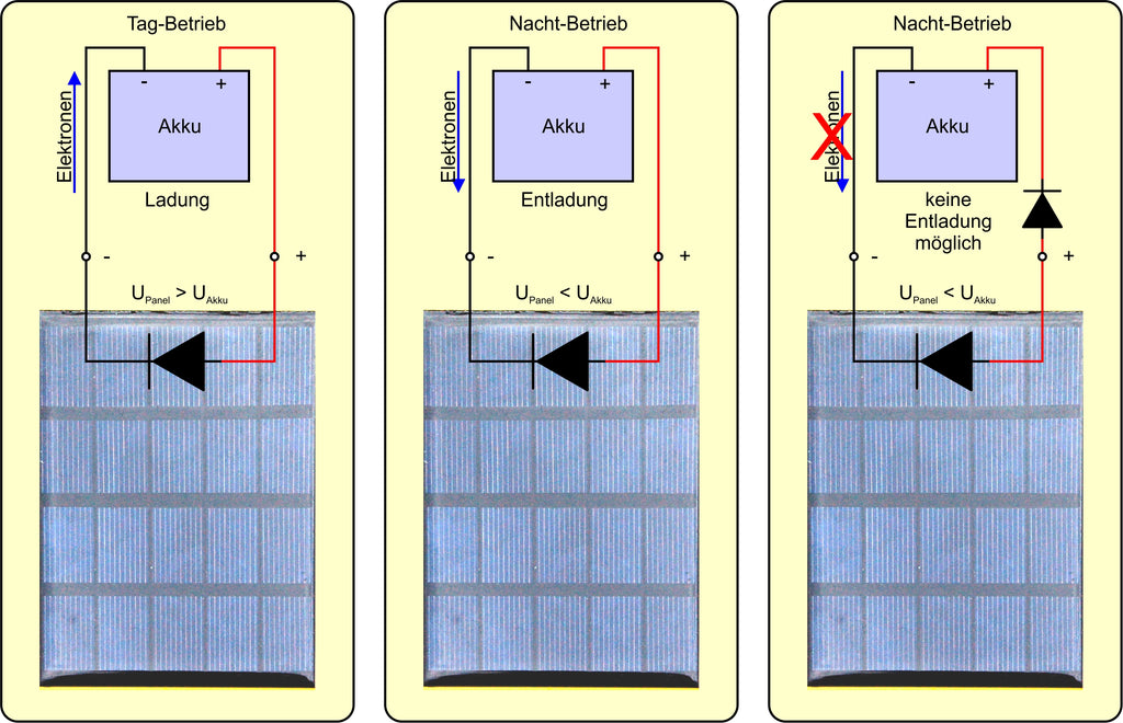
Image 4: Charging a battery from a solar panel
Such a discharge protection diode is also necessary if several panels are to be connected in parallel. This prevents the current supplied by the other panels from being discharged by the shaded panel when one of the panels is shaded.

Image 5: Solar panels in parallel - higher amperage

Image 6: Solar panels in series - higher voltage
The MPP Finder
My first experiments on the subject of MPP were done by hand. By means of volt- and ammeter and various resistors, I recorded the values for the U-P-characteristic of a panel. This brought the expected result but was much too elaborate for me to investigate different parameters like irradiation, parallel, and series connection.
So I needed a measuring servant, which I found in the ESP32. The tasks of a corresponding circuit were:
- An actuator for the change of the load
- A measured value acquisition
- A transmission of the data to the PC as simply as possible
Click! - Of course, I could use a buck converter as an actuator, which is controlled by a PWM signal from the ESP32. A high load resistor with a resistance value of a few ohms as a "consumer" is made to sweat by the step-down converter with a dosable amount of energy. The duty cycle of the PWM signal is quasi the valve for the energy arriving at the resistor from the solar panel. Thus, the converter does not primarily work here as a voltage or current regulator, but as a program-controlled, variable load.
However, there were problems with the measured value acquisition. The ESP32 with its many modules on it is a nice "egg-laying" pig, but first of all the voltage characteristic of the ADCs is anything but linear, and secondly, the voltage measurement only starts at approx. 150mV. For a current measurement in the range up to 500mA by means of a measuring resistor of 0.1 Ohm (UShunt = 50mV), no measured values could have been recorded without amplification.
While searching for a better solution I came across a BOB (Break-Out-Board) with the IC INA219. For my purposes just ideal, because it can capture voltages up to 32V and currents up to 3.2A and in addition also deliver the power in watts via the I2C bus to the controller - Bingo!
The acquired data is stored in a file on the ESP32. The files are transferred to the PC with Thonny and evaluated there in a spreadsheet.
The circuit

Image 7: MPP-Finder - circuitry
The details and operation of the circuit of the converter I have described in the first episode in detail. According to the description, the solar panels used should deliver a power of up to 1.5W at voltages of up to 6.3V. This corresponds to a current of up to 0.3A. So when three panels are connected in parallel, about 1A would be expected. In order for this current to flow when the valve is fully open, the load resistance must have a value below 5 ohms.
The OLED display informs about upcoming actions and finally provides the U-P characteristic curve for a first evaluation of the measurement.
The powerline.py program
In the beginning, the toolbox is filled, and I import various modules. We need the I2C-bus for conversation with the INA219 and the OLED display, PWM for the control of the converter, and of course the module ina219. To control the ESP32 I need the module buttons, also for the file management listdir and remove from the module os.
# powerline.py
from machine import SoftI2C,Pin,PWM
from time import sleep
from oled import OLED
from ina219 import INA219
import buttons
from os import listdir, remove
from sys import exit
Then the preparations begin. I create an I2C bus instance, with which I also instantiate the display object. Clear the display and set full contrast. We work in a bright environment.
i2c=SoftI2C(Pin(22),Pin(21))
d=OLED(i2c)
d.clearAll()
d.setContrast(255)
The measurement resistor on the INA219-BOB has 100mΩ, we expect currents up to 800mA. With 128 single measurements, each of them corresponds to one pixel in the OLED display. The step size for the PWM values from 0 to 1024 is obtained by dividing 1024 / by the number of steps.
shunt = 0.1  # Ohm
imax=0.8 # ampere
steps=128
step=1024/steps
The constructor of the class INA219 asks for a whole set of arguments, all of which except for i2c are all optional. ModeBoth requests the acquisition of bus and shunt voltage, Samp4 stands for a resolution of 12 bits with 4-fold oversampling, PGA2 sets the attenuator to 1/2 and Ubus16V allows bus voltages up to 16V.
ina=INA219(i2c,mode=INA219.ModeBoth,
           busres=INA219.Samp4,
           shuntres=INA219.Samp4,
           shuntpga=INA219.PGA2,
           ubus= INA219.Ubus16V,
           Imax=imax,
           Rshunt=shunt)
t is a button object at GPIO0. The flash button of the ESP32 closes against GND, therefore invert is set to True. This turns the 0 at GPIO0 into a True for the return of the waitForTouch() method. The button gets the name Start and the internal pullup resistor is switched on. The PWM signal is supplied by pin GPIO5 with a frequency of 50kHz. With a duty cycle of 1023, the BC337 switches through and pulls the gate of the IRLZ24 to GND potential, which blocks the MOSFET (see Figure 6) and disconnects the load from the panel. The open circuit voltage is now present at the panel.
t=buttons.Buttons(0,invert=True,pull=True,name="Start)
pwmPin=5
gate=PWM(Pin(pwmPin),freq=50000,duty=1023)
Now I define some passages that are used multiple times as functions. output() receives in the position parameter firstline up to 16 characters, which are output in the first line of the OLED display. With *other (up to five) further position parameters can be fed with strings. further represents a list with the passed arguments, which are retrieved in the for loop and end up in the display in the subsequent lines.
def output(firstline,*other):
    d.clearAll()
    d.writeAt(firstLine,0,0)
    for z in range(len(further)):
        d.writeAt(more[z],0,z+1)
The complex function result() reads the file whose name is specified in the name and filters out the MPP from the data. The file is fed with measured values in the measurement loop.
def result(name):
    try:
        n=0
        pmax=0
        umpp=0
        impp=0
        pulsmpp=0
try to catch errors that happen when reading the file, for example, if the file does not exist. The counter for the measured values and the positions for the MPP is reset, and the lists for the measured values are cleared.
The with-structure allows access to the file to be read name via the file handle f without having to close the file explicitly. It is closed automatically when the with-block is exited. The for loop iterates over the file entries. The lines are freed from carriage returns (\r) and line feeds (\n) and output to the terminal. I have the commas replaced by decimal points and split the line at the semicolons into single values, which I convert to numeric values so I can apply the arithmetic comparison to them. If the current value of the power P[n] is larger than the maximum found so far, I memorize it, with it also the values for the bus voltage and the current intensity, as well as the PWM value. Finally, the number of read values is increased.
        with open(name,"r") as f:
           for z in f:
               z=z.strip("\n\r")
               print(z)
               z=z.replace(",",".")
               u,i,p,pulse=z.split(";")
               U.append(float(u))
               I.append(float(i))
               P.append(float(p))
               pulse.append(int(pulse))
               if P[n] > pmax:
                   pmax=P[n]
                   umpp=U[n]
                   impp=I[n]
                   pulsmpp=Pulse[n]
               n+=1
Another try catches a division by zero error that can occur if pmax or the maximum of the voltage values should be 0 for some reason.
The maximum power is fitted into the 64-pixel display height, the maximum occurred voltage (= open circuit voltage of the module) into the 128-pixel display width. After the display is cleared, the for loop places the points in the U-P diagram there. The MPP and the corresponding voltage are output in the display and in the terminal.
        try:
            pfactor=63/pmax
            ufactor=127/max(U)
            print("ufactor=",ufactor)
            d.clearAll()
            for num in range(n):
                pos=63-int(P[num]*pfactor)
                x=int(U[num]*ufactor)
                #print(num,x," ",U[num]," ",pos)
                d.setPixel(x,pos,1)
            d.writeAt("Umpp={:.2f}V".format(umpp),0,4)
            d.writeAt("Pmax={:.2f}W".format(pmax),0,5)
            print("MPP: Umpp={:.2f}V Impp={:.2f}A Pmax={:.2f}W Duty={:.2f}% ({})".\
                  format(umpp,impp,pmax,pulsmpp/1023*100,pulsmpp))
The except blocks provide information about any errors that may have occurred.
        except ZeroDivisionError:
            print ("Divide by 0 - Error")
            d.clearAll()
            d.writeAt("Divide by 0!",0,3)
            d.writeAt("last measurement",1,4)
            d.writeAt("erroneous",3,5)
    except OSError:
        print("Error reading from file")
        output("FILE ERROR")
The function test() generates the data for a parabola with the function result() can be tested. With n I pass the serial number for the file name, which I then pass to the function result() function. For this to work from the command line, the program must use powerline.py and must have run at least once.
def test(n):
    f=open("power"+str(n)+".txt","w")
    for x in range(steps):
        y=-(0.01587*(x-64)**2)+63.0
        s="{:.2f};7.24;{:.2f};512\n".format(x,y)
        f.write(s)
    f.close()
With the function findName() I determine the next file name not yet used. The names consist of the string "power" and an appended serial number, as well as the extension ".txt". The local variable free is set to False. It indicates whether a name is available.
As long as free is not True in the while loop with the counter n starting at 0, a name is assembled and it is checked whether the file can be opened for reading. This is the case if the file with this name exists. Otherwise, an OSError exception is thrown.
To end the loop-free to True the name is printed in the terminal and n and the name is returned.
def findName():
    n=0
    free=False
    while not free:
        try:
            name="power"+str(n)+".txt"
            with open(name,"r") as f:
                pass
            n+=1
        except OSError:
            free=True
            print(name)
            return n,name
The key t key is used to control the main program. In the beginning, a new measurement can be triggered with it. I have the information output in the display. Then 3 seconds remain to press the key. The buffer of one second ensures that the key has been released. I note the key state in measure. True stands for "key pressed". If the timeout has expired None returns.
output("FLASH BUTTON","FOR MEASUREMENT","PRESS")
MEASUREMENT=t.waitForTouch(t,delay=3)
t.waitForRelease(t,delay=1)
Only when measuring is to be done, I am asked if the existing measured value files should all be deleted. If this is the case (press the key again), then I get a list of the existing files. If the first five characters in the file name are "power", the file name is output and the file is deleted. This filter saves the file main.py, which contains the program and the module files from being deleted as well. After that, I search for an available filename and get back the number and filename. This allows one of two actions to be performed.
if measurement:
output("FLASH BUTTON"," ","TO DELETE","THE FILES")
clearFiles=t.waitForTouch(t,delay=3)
if clearFiles:
for file in listdir():
if file[:5]=="power":
print(file)
remove(file)
counter,name = findName()
Is measurement None, then the key t key was not pressed at the beginning. This leads to the output of the trace of the last measurement in the OLED display, as well as the measured values in the terminal. In counter is the number of the next free file name. Counter - 1 thus addresses the last available measurement.
else: # Display result
    name="power+str(counter-1)+".txt"
    result(name)
With measurement equal True starts a new measurement series. Try blocks to write errors to the file. I open a file for writing, and set the PWM value to 1023 (MOSFET locks) and the value counter to 0.
if measurement:
    output("MEASUREMENT","STARTED")
    error=False
    try:
        with open(name,"w") as f:
            pulse=1023
            n=0
As long as the pulse is greater than 0, single measurements are made. The step size step is a floating point number. It is calculated after each measurement of pulse subtracted. pulse is therefore also of type float. For using pulse as a PWM value it must be made an integer. The number of the measurement and the pulse width are shown in the OLED display.
            while pulse>=0:
                intpulse=int(pulse)
                gate.duty(intpulse)
                d.writeAt("{}. {}           ".format(n,intpulse),0,3,True)
getCurrent() and getPower() can throw an overflow exception, which I catch with a try. In this case error at True and the power is assigned the value -1.
                try:
                    u=ina.getBusVoltage()
                    i=ina.getCurrent()
                    p=ina.getPower()
                except OverflowError:
                    u,i,p=0,0,-1
                    error=True
The measured values are assembled into a string with line feed, where the semicolon serves as a separator. When a measured value file is imported as a CSV file into a calculation program, the program recognizes the separation of the values and can divide them into different columns. In order for the calculation tool to interpret the strings as numerical values, the decimal points must be converted into commas. This is done by the method replace(). The string is written to the file and the pulse is decreased by the step size. When the block ends, the file is automatically closed.
                s="{:.2f};{:.2f};{:.2f};{}\n".\
                    format(u,i,p,intpulse)
                s=s.replace(".",",")
                f.write(s)
                pulse-=step
                n+=1
After finishing the measurement series I set the duty cycle to 1023 and disconnect the panel from the load. This is followed by the output of the result and the handling of any errors that may have occurred.
        gate.duty(1023)
        result(name)
        if error:
            d.writeAt("OverflowERROR",0,0)
    except OSError:
        print("Error writing to file")
        output("FILE ERROR")
Program execution in the open
So that the program can be executed in the Pampa also without a PC, it must be called under the name main.py on the ESP32. For this, I always create a new file and copy the program text, here is the one from powerline.py, and save the new file directly on the ESP32 under the name main.py. With every restart or reset the ESP32 will now automatically start with a new run.
File transfer to PC
The evaluation of the measurements is done on the PC. I use Libre Office Calc for this. Which steps are necessary for this, I show now.
Mark the desired files in Thonny in the MicroPython device area.

Image 8: Sending files to the PC
Right-click on the selection to open the context menu. Download files to the PC.

Image 9: Start download
The files are now located in the working directory of Thonny. Open a file in an editor and select the entire text. Copy it to the clipboard.

Image 10: Open file in editor
Now start Libre Office Calc. Right click on the field A1 opens the context menu -. Insert contents - Insert contents.

Image 11: Insert content

Image 12: Use text import
At Separation options set the check mark at Semicolon - OK
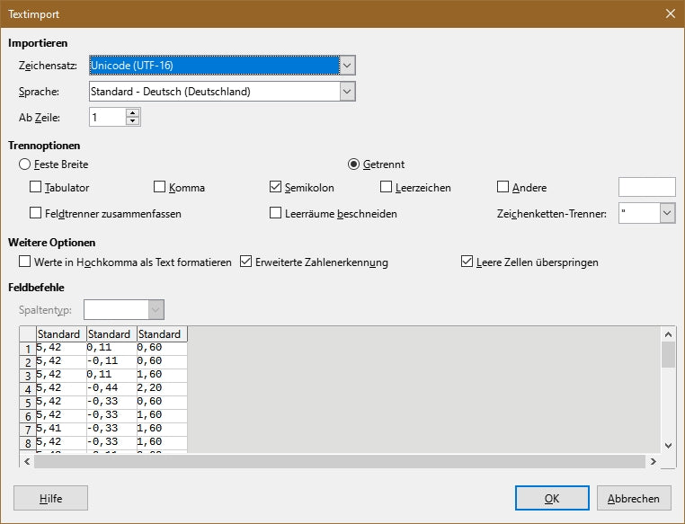
Image 13: Text import settings
Select the columns A, B and C.

Image 14: Mark columns
Click on Insert diagram.

Image 15: Insert diagram
Select XY Scatterplot Points or Points and lines

Image 16: Diagram wizard
Finish.

Image 17: Finished diagram
The blue curve is the U-I characteristic. Where it bends downwards is the maximum of the red curve, the MPP.
Yes, transferring the data from the ESP32 to the PC via USB cable is an option, but it would be nicer if the data would end up on the PC simultaneously, right after each measurement. Exactly this solution is content in the next episode. For the transfer I will use the radio properties of the ESP32. This is easier and faster. After all, I don't run after the bus when I'm already sitting in it.
So, see you then!


2 comments
Jürgen
Die habe ich von Reichelt.
https://www.reichelt.de/index.html?ACTION=446&LA=3&nbc=1&q=l-xhbcc330
Karl-Heinz
Hallo,
trotz intensiver Google suche ist es mir nicht gelungen eine adequate Drossel zu finden.
Können Sie mir einen Link zu Ihrer Drossel geben.
Gruß
Karl-Heinz