
The MQTT client from the second episode This series of topics is growing today. An ESP8266 D1 Mini should measure the flow and return temperatures of the heating system and provide them with the Mosquitto server. It will also wait for the entrance to two signals, through which the circulation pump and the burner of the heating are switched via two relays.

Image 1: MQTT client - heating
As a third module, I present an MQTT monitor whose "boss", an ESP32, spends the data of the entire system on an LCD keypad and sends switching commands to the other two clients via the built-in buttons. I am pleased that you are there again. Welcome to this series with today's title
3. Expansion of the MQTT-Home system
In the Second episode of this series, I had already mentioned that the use of MQTT is enormously scalable for a control and surveillance system. Replace or complement new units.
The two modules that I present to you today do exactly that, we complement a measuring point and a control unit. The latter can fall back on the data of the new measuring station and that of the previous ones. No interventions are necessary on the Mosquitto broker. If a station is removed, the server lacks this information and asks for a client, it will simply not receive any new values. But there are also no error messages or system crashes. Likewise, commands to the removed station are no longer called up, upcoming actions are only not carried out. The server as an intermediary has no problem. The conclusion is that modules of this series do not all have to be realized. The system will work when the Raspi runs with the broker and at least one module is available as a publisher and/or subscriber.
Hardware
The following parts are needed for the two stations that we want to build today.
|
1 |
|
|
1 |
|
|
1 |
I2C IIC Adapter Serial interface for LCD Display 1602 and 2004 |
|
2 |
D1 Mini Nodemcu with ESP8266-12F WLAN module or |
|
2 |
|
|
2 |
Voltage supply 5V, 500mA for the ESP32/ESP8266 |
|
1 |
2 x 1m cable DS18B20 Digital stainless steel temperature sensor Temperature sensor |
|
1 |
|
|
1 |
|
|
various |
|
|
1 |
Raspberry Pi with 16GB Class10-SD card |
|
1 |
Voltage supply 5V; 2.5A for the Raspi |
|
1 |
Network cable |
The software
For flashing and the programming of the ESP32:
Thonny or
Firmware used:
Please choose a stable version
The Micropython programs for the project:
dashboard.json (episode 4)
Micropython - Language - Modules and Programs
To install Thonny you will find one here Detailed instructions. There is also a description of how the Micropython firmware On the ESP chip burned becomes.
Micropython is an interpreter language. The main difference to the Arduino IDE, where you always flash entire programs, is that you only have to flash the Micropython firmware once on the ESP32 so that the controller understands Micropython instructions. You can use Thonny, µpycraft, or ESPTOOL.PY. For Thonny I have the process here described.
As soon as the firmware has flashed, you can easily talk to your controller in a dialogue, test individual commands and see the answer immediately without having to compile and transmit an entire program beforehand. That is exactly what bothers me about the Arduino IDE. You simply save an enormous time if you can check simple tests of the syntax and hardware to try out and refine functions and entire program parts via the command line before knitting a program from it. For this purpose, I always like to create small test programs. As a kind of macro, they summarize recurring commands. Whole applications then develop from such program fragments.
Autostart
If the program is to start autonomously by switching on the controller, copy the program text into a newly created blank tile. Save this file under boot.py in WorkSpace and upload it to the ESP chip. The program starts automatically the next time the reset or switching is on.
Test programs
Programs from the current editor window in the Thonny-IDE are started manually via the F5 button. This can be done faster than the mouse click on the start button, or via the menu run. Only the modules used in the program must be in the flash of the ESP32.
In between, Arduino id again?
Should you later use the controller together with the Arduino IDE, just flash the program in the usual way. However, the ESP32/ESP8266 then forgot that it has ever spoken Micropython. Conversely, any espressif chip that contains a compiled program from the Arduino IDE or AT-Firmware or Lua or ... can be easily provided with the Micropython firmware. The process is always here described.
Monitoring of the heating - homework solution
Of course, the monitoring and control of heating are more than just the structure described below, which only captures the temperatures of the lead and return and can switch the burner and circulation pump. There should also be external sensors, apartment thermostats, time circuits, etc.. All of this can still flow into our system.
The circuit
When building the circuit, an ESP8266 D1 mini was at hand. One is just as well suited as Amica Or an ESP8266-node-McU. The easiest way to provide energy is a suitable USB cable and a 5V plug-in power supply. The program text must be a boot.py for an autonomous start of the program in the flash of the ESP8266. For the program dhtclient.py from the previous contribution, we invite it to Thonny and immediately save it under the name Boot.py in WorkSpace. Now Boot.py only has to be uploaded to the ESP8266. After a reset, the controller starts independently. We can observe the progress of the flashing signs.
A note on the ESP8266 Node-MCU V3. This board can be on the pin Vin Although 5V is supplied with an external source, the 5V from the USB connection does not provide the 5V. In order to switch the relays on the duo module, this must be supplied with its own 5V line.
The double relay module used can also be used for switching performance up to 300W on 230VAC. The medium-voltage contacts of the relays are sufficiently separated from the low-voltage side by an air gap. Modules without this gap should not be used larger than 50 V for switching stresses. The relays are low-level triggered. This means that the no-contact (Normal Open) is closed when the inx (x = 1 or 2) GND level is located at the input.

Image 2: Relay module - underside
The button has no function at the moment but can be used itself, or replaced by a digital sensor, as an input medium for publishing messages about the broker. The only condition is that at the start time on the PIN GPIO0 high level. Otherwise, the ESP8266 switches to flash mode.
The LED signals the following conditions with the three colors:
- Blue: long - blinking for short; Connection to the WLAN router
- Green: short - long flashing; Heartbeat of the main loop passage
- Red: In short - short - briefly flashing; Error display
Various pre -resistances have been used to achieve about the same brightness as the LEDs.

Image 3: circuit heating client
The program for heating control
Based on the heating module, I want to show that the rededication of an existing unit to other sensors and another controller can be feasible without major changes in an existing program environment.
The changeover from a DHT22 to two DS18B20 requires a few changes compared to the program dhtclient.py from the Second blog post.
Instead of the DHT module, we import the modules OneWire and DS18x20
From OneWire import OneWire
From DS18x20 import DS18x20
The pin assignment differs from the DHTClient because both circuits were developed independently of one another. Of course, you can also make sure from the outset that the occupations remain largely the same, then you save yourself rewriting the pin numbers. PIN 14 is handed over to the constructor of the DS-Pin as a one-time object. Then we read the ROM codes of the DS18B20 chips, through which we can address the sensors individually. Two pins for controlling the relay are added.
ds_pin = Pin code(14)     # D7@ESP8266
DS = DS18x20(OneWire(ds_pin))
crisps = DS.scan()
print("Crisps",crisps)
relheating=Pin code(13,Pin code.OUT,value=1)
relepump=Pin code(12,Pin code.OUT,value=1)
Further topics for publishing and subscribing are supplemented or replaced by the previous ones.
Topic advance="Heating/lead"
topicrueck run="Heating/Ruecklauf"
Topic pump="Heating/pump"
topic="Heating/machine"
Topic pump done="Heating/pump/Done"
Topic="Heating/machine/Done"
The fat-formatted lines in the ReaddS18B20 () function replace part of the Readdht () function. When installing the sensors, we pay attention to the correct assignment of chip0 to the lead and chip1 for the return. We get the two temperature values again as a tufa in the return.
def readds18b20():
    try:
        DS.convert_temp()
        sleep(0.85)
        leader=DS.read_temp(crisps[0])
        curse=DS.read_temp(crisps[1])
        print("Preliminary run, Ruecklauf",leader,curse)
        return leader, curse
    except Oserror AS E:
        print("Sensorf errors ---->",E)
        return None
In the function connect2broker() If we change the subscription to the new topics and, if necessary, adapt the output boards. The latter can be omitted in the production system without damage.
    client.subscriber(Topic pump)
    client.subscriber(topic)
In the function MessageAeart() If we change the existing query and add a second one. After each campaign, we publish feedback for the client.
    IF topic == Topic pump:
        IF MSG=="at":
            relepump.value(0)
            client.publish(Topic pump done, "AT")
        Else:
            relepump.value(1)
            client.publish(Topic pump done, "OUT OF")
    IF topic == topic:
        IF MSG=="at":
            relheating.value(0)
            client.publish(Topic, "AT")
        Else:
            relheating.value(1)
            client.publish(Topic, "OUT OF")
Finally, in the main loop, we adapt the passage in which the sensors are queried and publish the new data. Everything else is taken from DHTCLIEN.PY unchanged.
while True:
    try:
        client.Check_MSG()
        IF sendnow():
            respect=readds18b20()
            IF respect is need None:
                leader,curse = respect
                leader = (B '{0: 3.1f}'.format(leader))
                curse =  (B '{0: 3.1f}'.format(curse))
                client.publish(Topic advance, leader)
                client.publish(topicrueck run, curse)
Here you will find the entire file heating.py as a download for comparison. Only about 18% of the program lines had to be adapted/supplemented.
Image 4: MQTT client - heating
Figure 4 reveals my trick for reversible assembly of assemblies on a baseboard. The gray plasticine is Eternite sealing mass. It does not stick to the fingers but holds the parts well and can be removed from the surface and the components without a residue.
Test of the heating client
It is time to carry out a test of the previous equipment. Is Mosquitto running on the Raspi? Then we start the program in Thonny heating.py And wait for the connection to the WLAN router and then to the broker, after which the temperature reports from the ESP8266 would have to appear in the terminal area at a 5-second distance.
Then we open a terminal to the Raspi. This has to happen now via Putty because there is no keyboard and no screen on the Raspi. We start Putty and open the connection to the Raspi, which we In the first part of the series have created and registered at the Raspi.

Image 5: Open putty
We subscribe to the Topics heating/lead and heating/recurrence and get the latest results immediately with every new scanning of the sensors on the heating client.

Image 6: Messages of the heating client
If we break off with Ctrl+C, we enter the following commands on the command line and observe the LEDs on the relay board. If the LEDs go on and out, the circuit and our program have passed the test.

Image 7: Publishing - We switch the heating
To see the feedback, we open a second terminal to the Raspi and enter the following subscription.

Image 8: Start subscription
From the publisher window, we give the switching commands again.

Image 9: Publishing - We switch the heating again to the rehearsal
The news from the heating client appears in the subscription window.

Image 10: Review of the feedback
Homework:
With a sound module (microphone and comparator) you can grasp the times when the burner runs. The heating.py program would have to send an MQTT message for evaluation if the burner switches on and turns off again. An MQTT client on the Raspi could subscribe to the messages and create statistics from them.
The ESP32 as a control center
Our two clients behave passively in a way because there are no operating elements on them (so far). This should change with the monitor client.

Image 11: MQTT monitor
The circuit of the MQTT monitor
An ESP32 receives all previously available MQTT messages but also allows the other two clients to be sent to the other two clients via the buttons of the LCD keypad. There the corresponding topics are subscribed to and converted into switching signals for the relays. In response, we receive the news that the clients publish after the switching process.
The DHTCLIEN.PY program is also used as the basis for programming for the monitor client. We also find the RGB LED for signaling the program states. Unfortunately, the display only has two lines, but I didn't want to do without the keys. With a small trick, you can switch three relays on and off with the 6 keys, although only five buttons can be queried via the analog input GPIO35. The module is actually designed for the Arduino Uno and has an RST key that we query us to misuse separately via GPIO0.
The keys are on the RST button on a resistance cascade. The voltage that sets on a button on the output A0 of the LCD keypad is used for its decoding. This happens in the module keypad.py. If necessary, the limit values of the areas in the constructor must be easily changed. However, the limits must not overlap and the key values should be in the middle of the area.

Image 12: Switch cascade
After the 5V from the LCD keypad supply there at A0 at idle, the voltage must be reduced to a size that is bearable for the ESP32. This is done by the voltage divider with 1kΩ and 2.2kΩ at the A0 output. At the GPIO35 input, the voltage values remain below 3.3V.
The display and thus the entire LCD keypad must be operated on 5V. The 5V connection on the ESP32, Pin Vin, is completely sufficient for this. We also supply the board again via the USB cable and a plug-in power supply of 5V. Part of the LCD connections are also raised to 5V. This means that the display cannot be connected directly to the ESP32. The i2C parallel converter with the PCF7485 therefore also takes over the function of a level converter. Its starting levels can only deliver up to a maximum of 1MA but can accommodate up to 25mA. This is exactly what we need to draw the inputs of the display to GND potential. The SCL line is held to 3.3V by the ESP32 and the PCF8574 can also increase the SDA line to no higher potential because we only treat it to 3.3V as a supply voltage. So everything is in cozy towels for the ESP32.
Incidentally, the lighting of the display cannot be switched off because it is firmly wired in inaccessible places.

Image 13: MQTT monitor circuit
We come to the program for the MQTT monitor. I had already indicated that the program of the DHT client is also the inspiration for this. We can remove the sensor part, we have to expand the subscription and publishing part and take care of the control of the LCD.
The monitor program
After removing the DHT import, we add the following modules. Class I2CBUS makes the operation of the interface a little more gripper. Keypad_LCD is the interface for the hardware treatment of the key query, while Keypad generally provides routines for the input and keyboard evaluation - wait for a button, get an ASCII sign, input function. LCD offers the same commands as far as the OLED class. PCF8574U_I2C is the hardware driver for the LCD processor and HD44780U delivers the commands that are used in the methods of LCD.
From I2CBus import I2CBus
From keypad import Keypad,Keypad_lcd
From LCD import LCD
From HD44780U import HD44780U, PCF8574U_I2C
Then we create the objects for the display and keyboard.
I2C=I2C(scl=Pin code(21),sda=Pin code(22))
Ibus=I2CBus(I2C)
D=LCD(I2C,ADR=0x27,cols=16,lines=2) # LCDPad on the I2C bus
D.clearall()
KPDDRV=Keypad_lcd()
KP=Keypad(KPDDRV,D)
We already know the topics. The variable buffers the status of the corresponding values for the display function.
topic=[
        "Heating/lead",
        "Heating/Ruecklauf",
        "Heating/pump",
        "Heating/machine",
        "Cellar/temperature",
        "Keller/humidity",
        "Keller/fan",
      ]
leader=0
curse=0
pump="OUT OF"
heating="OUT OF"
temperature=0
wet=0
fan="OUT OF"
The display on the display must be distributed on three screens. The variable screen is the corresponding pointer. nextmsgdelay Specifies the time to change the screen in milliseconds. The pins for the status LEDs are redistributed and the usual key PIN is declared.
screen=0
nextmsgdelay=1500
status=Pin code(27,Pin code.OUT,value=0) # blue = 2
onair=Pin code(26,Pin code.OUT,value=0) # gruen = 1
error=Pin code(25,Pin code.OUT,value=0) # red
LED=[error,onair,status ]
red,green,blue=0,1,2
button=Pin code(0,Pin code.IN,Pin code.Pull_up)
Perhaps you noticed that the seven subscribed topics were defined in the form of a list. This is where the reason for this comes in.
    for T in topic:
        client.subscriber(T)
        print(T)
In the largely adopted function connect2broker() we can now do the subscriptions in a simple for loop instead of listing them individually.
Also, the function MessageAeart() keeps your head, only the list of queries must be expanded. The data received are stored in the variables provided for the later display. So that changed values from the function can be found back to the main program, the variables must be global be declared.
    global leader,curse,pump,heating
    global temperature,wet,fan
    IF theme == topic[0]:
        leader=float(MSG)
    IF theme == topic[1]:
        curse=float(MSG)
    IF theme == topic[2]:
        pump = MSG
    IF theme == topic[3]:
        heating = MSG
    IF theme == topic[4]:
        temperature = float(MSG)
    IF theme == topic[5]:
        wet = float(MSG)
    IF theme == topic[6]:
        fan = MSG
The function is a new show screen(), which reports the database in three screens. The number of the screen is handed over as a parameter. The display is deleted before each issue.
def show screen(NBR):
    D.clearall()
    IF NBR == 0:
        D.writer("K-Temp: {} *C".format(temperature),0,0)
        D.writer("K-Hum: {} %".format(wet),0,1)
    IF NBR == 1:
        D.writer("V-Run: {} *C".format(leader),0,0)
        D.writer("R-Run: {} *C".format(curse),0,1)
    IF NBR == 2:
        D.writer("Up: {}; HZG: {}".format(pump.upper(),\
                                   heating.upper()),0,0)
        D.writer("Fan:{}".format(fan.upper()),\
                                   0,1)
The WLAN registration remains as usual. In the main loop, we first ask for the keys. The waiting time for querying the buttons using the Kp. Waitforkey () method is set at 0.5 seconds. This is sufficient and ensures a liquid grinding run. The assignment of the keys can be changed as desired. It is shown in the table.
|
button |
Value |
function |
|
Select |
4 |
Pump out |
|
Leaf |
3 |
Pump on |
|
Up |
1 |
Brenner on |
|
Down |
2 |
Burner |
|
Right |
0 |
Fan |
|
RST |
|
Fan on |
Shownow () is the function that indicates the return value of True that the timer has expired for displaying the current screen. Time-out() actually gives a reference to the interior defined inside Closure compare() back that the variable shownow is assigned.
The keyboard query is now where the function of the function has been available for reading the temperature values. Depending on the key value, the corresponding message is published.
shownow=Time-out(nextmsgdelay)
while True:
    T=KP.Waitforkey(0.5)
    IF T == 4:
        client.publish("Heating/pump", "out of")
    elif T== 3:
        client.publish("Heating/pump", "at")
    elif T== 1:
        client.publish("Heating/machine", "at")
    elif T== 2:
        client.publish("Heating/machine", "out of")
    elif T == 0:
        client.publish("Keller/fan", "out of")
    Else:
        passport
    T=-1
    IF button.value() == 0:
        client.publish("Keller/fan", "at")
    try:
        client.Check_MSG()
        IF shownow():
            show screen(screen)
            shownow=Time-out(nextmsgdelay)
            screen=(screen + 1) % 3
            flashing(0.03,0.02,green)
    except Oserror AS E:
        flashing(0.2,0.3,red,inverted=True)
        flashing(0.2,0.3,red,inverted=True)
        flashing(0.2,0.3,red,inverted=True)
        residual()
    sleep(0.1)
With every grinding run, we are now checking the client.check_msg() whether there is a new message in MessageAeart() is decoded. A return value of the timer function shownow() shows us in the case of True that the next screen must be displayed. We then also re-enact the timer and increase the screen number modulo 3. The part of the screen number always delivers the values 0, 1, and 2 in the same cycle.
Also, this one Program monitor.py is download ready. Is your structure ready? Do the other two clients run? Is Mosquitto ready to receive? Then we start the test of the monitor unit.
After the usual LED signals for connecting buildings, the green LED should flash over the two-second rhythm. The display refresh with the value of nextmsgdelay All 2000ms. The display should now display the following screens.
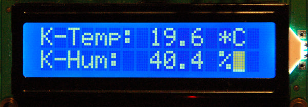
Image 14: Keller - temperature and air humidity

Image 15: heating - lead - return

Image 16: Keller, heating-switching states
When pressing the keys, the corresponding relays must be addressed at the clients and the switching states on the display must be shown. If all of this works as desired, knock on the shoulder admiringly. The two hardware parts mastered them brilliantly.
In the next episode, we will take care of the Raspi, more precisely about Node-Red. We get a control center that can be reached on the LAN via a browser. If this is to be accessed worldwide, then release must be set up in the router to the Node-Red server on the Raspi. We will also look at a way that establishes a time control of the heating. The Raspi also helps us.
In the meantime, you could think about how a temperature sensor could possibly be integrated into the system in the apartment. Have fun tinkering, programming, and brooding.
Of course, this episode is again available for printing and saving PDF files for download.


11 comments
Bernd-Steffen Großmann
@Mena Palm: Bei einigen Breadboards kann man die „power-rails“ (Stromversorgungs-Schienen) abnehmen. Dann kann man zwei Breadboards nebeneinander stecken und dann passt auch ein ESP32-Node (über beide) gerade drauf. Ich verwende am liebsten Universal-Lochraster-Platinen mit den passenden Stecksockeln (hier 2 Stk. mit 2×9 Kontakten). Aber zur Zeit ist das Wetter zu schön, um im „dunklen“ Hobbykeller zu sitzen! ;0) mit freundlichem Gruß Bernd-Steffen Großmann
Jürgen
@ Mena Palm
Eine Sache ist mir noch aufgefallen, woher kommt das @ 0?
I2CBus-Tools OK @ 0
Das steht in meinem Konstruktor nicht drin.
class I2CBus:
def init(self,I2c,hwadr=HWADR):
self.i2c=I2c
self.hwadr=hwadr
print(“I2CBus-Tools OK”) ????
Die Rückmeldung [] von i2c.scan() ist ein weiteres Zeichen für Kabelprobleme oder vertauschte Leitungen.
Und einen Tipp habe ich auch noch wegen der X-Beine des ESP. Wenn Sie zwei Breadboards parallel legen, passen die Stifte gerade rein. Ich verlöte meine Platinchen alle nach der Methode: Stiftleisten ins Breadboard, Platine drauf und dann löten.
Viele Grüße
J. Grzesina
Mena Palm
Guten Tag, allerseits,
ich habe etwas über das Löten gelernt: NICHT lÖten ist blÖd!
Jetzt funktioniert alles einwandfrei.
Vielen Dank für die Hilfe und Grüße von
Mena Palm
Mena Palm
Danke für die ausführliche Antwort!
Ich habe das mal ausprobiert, mit ernüchterndem Ergebnis:
>>> %Run -c $EDITOR_CONTENT
I2CBus-Tools OK @ 0
>>> i2c.scan()
[]
>>>
Aber:
>>> %Run -c $EDITOR_CONTENT
I2CBus-Tools OK @ 0
>>> i2c
SoftI2C(scl=21, sda=22, freq=500000)
>>>
Und nu? Vielleicht sollte ich am Wochenende doch mal zum Lötkolben greifen. Dann ist er halt für alle Zeiten x-beinig. Ich werde berichten.
Viele Grüße von
Mena Palm
Jürgen
@ Mena Palm
…
File “hd44780u.py”, line 199, in pcfWrite
OSError: [Errno 116] ETIMEDOUT <<<<<<
Ein Timeout beim Zugriff auf den LCD-Adapter über I2C lässt eindeutig darauf schließen, dass die Busverbindung nicht funktioniert, was angesichts der Tatsache, dass die Stiftleisten nicht verlötet sind, wie Sie schreiben, nicht verwundert. Fügen Sie doch einmal in der Datei monitor.py in die freie Zeile 27 folgenden Befehl ein und geben Sie dann auf der Console den darauf folgenden Befehl ein.
i2c=I2C,sda=Pin(22))
ibus=I2CBus(i2c)
sys.exit() <<<<<<<<<<<<<<<<<<<<<<<<<<<<<< natürlich ohne die Kleinerzeichen
>>> i2c.scan()
39 <<<<<< Ausgabe
Ist die Ausgabe nicht 39 = 0×27, dann haben Sie ein Problem mit den I2C-Leitungen, einen falsch gejumperten PCF8574, eine defekte Adapterplatine oder einfach nur ein defektes Kabel. Was mir auch schon passiert ist, in der Hast habe ich die Kabel SDA und SCL gekreuzt.
Die Warnungen habe ich im Kommentar an Herrn Großmann schon behandelt, das ist eine Sache, die auf das Konto der Micropython-Entwicklergruppe geht aber noch nicht die Schnittstelle und den Bus betrifft, sondern nur den Kernel von Micropython. Ihr Problem sehe ich in der Hardware und den Verbindungen.
Erfolgreiche Suche
J. Grzesina
Bernd-Steffen Großmann
Hier noch die Fehlermeldung bei dem “einfachen” Esp32 mit Adapter.
1. Version; MicroPython v1.18 on 2022-01-17; ESP32 module with ESP32
2. Fehlermeldungen: Warning: I2C is deprecated, use SoftI2C(…) instead
I2CBus-Tools OK
Traceback (most recent call last):
File “”, line 26, in
File “lcd.py”, line 12, in init
File “hd44780u.py”, line 138, in init
File “hd44780u.py”, line 167, in backLight
File “hd44780u.py”, line 199, in pcfWrite
OSError: [Errno 116] ETIMEDOUT
Mit dem ESP32-Wroover-Module bzw. Dev.kit funktioniert es mit derselben firmware 1.18 und den genannten Python-Dateien. Da bin ich jetzt etwas ratlos.
Mit freundlichen Grüßen,
Bernd-Steffen Großmann
Mena Palm
Bitte, ich brauche etwas Starthilfe: Teil 1 und 2 der Reihe funken im Haus lustig vor sich hin, aber an Teil 3 beiße ich mir die Zähne aus: Die Relais an ‘heizung.py’ schalten nur außerordentlich sporadisch, entsprechend nützt es auch nichts, dieses Thema zu subscriben, da kommt nichts. Woran es liegt … keine Ahnung. Wenigstens konnte ich ihm abgewöhnen, mein Arbeits- Bastel- und Schlafzimmer die ganze Nacht blau auszuleuchten. Ich habe dem Inverted-Teil von blink() am Ende eine Zeile mit off spendiert.
Noch schlimmer ist aber ‘monitor.py’ dran. Ich mag dem ESP32 die Header nicht anlöten, denn der steht da ganz x-beinig über der Trennung zwischen zwei Breadboards, anders hätte ich nur auf einer Seite Kabel anstecken können. Nun ist das halt so ein Wackelkandidat, der nicht immer alle Komponenten mit Strom versorgt. Macht aber nichts, denn das Programm will partout nicht starten und gibt immer nur einen Schwall Fehlermeldungen von sich, mit denen ich noch nichts anzufangen weiß (beruflich spreche ich Delphi, nicht Python, da bin ich am Lernen):
>>> %Run -c $EDITOR_CONTENT
I2CBus-Tools OK @ 0
Traceback (most recent call last):
File “”, line 27, in
File “lcd.py”, line 30, in init
File “hd44780u.py”, line 138, in init
File “hd44780u.py”, line 167, in backLight
File “hd44780u.py”, line 199, in pcfWrite
OSError: [Errno 116] ETIMEDOUT
>>>
Irgendwelche Ideen, woran das liegen kann?
Die Warnung bezüglich I2C und SoftI2C habe ich schon wegbekommen, der Rest ist mir ein Rätsel. Ich bin dankbar für jede Hilfe.
In gespannter Erwartung
Mena Palm
Jürgen Grzesina
Nach einem Reset, bekommen Sie die Release-Nummer der Firmware mitgeteilt, falls der ESP32 schon vor längerer Zeit geflasht wurde, und Sie die Version nicht mehr wissen.
….
MicroPython v1.18 on 2022-01-17; ESP32 module with ESP32
Type “help()” for more information.
Das ist wichtig, für das Verhalten der I2C-Schnittstellen. Es gibt eine Hardware-Lösung mit fest vorgegebenen Pins. Deren Deklaration sieht so aus:
>>> from machine import I2C,Pin
>>> i2c=I2C
>>> i2c
I2C
Ich verwende die Software-Lösung mit Bitbanging, wo man die GPIO-Pins selbst angeben kann. Das sieht entweder so aus:
>>> i2c=I2C,Pin(22))
Warning: I2C is deprecated, use SoftI2C(…) instead
>>> i2c
SoftI2C(scl=21, sda=22, freq=500000)
Diese Schreibweise ist veraltet und sollte duech folgende ersetzt werden:
>>> from machine import SoftI2C,Pin
>>> i2c=SoftI2C(Pin(21),Pin(22))
>>> i2c
SoftI2C(scl=21, sda=22, freq=500000)
Weitere Hilfestellung kann ich leider nur geben, wenn Sie die Fehlermeldungen posten.
Viele Grüße
J. Grzesina
Bernd-Steffen Großmann
Sie haben vollkommen recht! Es lag an einem schlechten Steckkontakt zwischen Display und I2C-Interface. Bisschen an den Kabeln gerüttelt und schon funktioniert es.
Ich hab jetzt die Schaltung mit dem ESP32-Monitor etwas modifizieren wollen und einen einfachen ESP32-Chip auf Adapterplatine ( https://www.az-delivery.de/products/esp-32-mit-adapterkarte ) eingesetzt. Zunächst war es schwierig, eine dafür passende, lauffähige Mikro-Python firmware zu finden, aber das gelang mir nach einigen Versuchen. Aber wenn ich nach dem Hochladen der vier „Hilfsprogramme“ das Monitorprogramm laufen lasse, kommt erst die Warnung, nicht mehr i2cbus sondern soft-i2c zu verwenden und danach kommen mehre Zeilen Fehlermeldung. Ich hab den genauen Text gerade nicht parat. Ich liefere das aber nach.
Mit freundlichem Gruß,
Bernd-Steffen Großmann
Mit freundlichen Grüßen,
Bernd-Steffen Großmann
Jürgen
Hieroglyphen, das klingt nach vertauschten Kabelanschlüssen auf dem 4-poligen Datenbus vom
PCF8574-Modul zur Display-Platine. Wenn Zeichen dargestellt werden, scheinen SCL, SDA und
die beiden Steuerleitungen, RS und E, zum Display zu stimmen. Foto und Zeichnung im Blog
stimmen überein, da kann also kein Fehler drin sein. Manchmal hilft es auch die Kabel auszutauschen, denn denkbar wäre auch ein Kabelbruch oder ein schlechter Steckkontakt. Sollten weiterhin Probleme bestehen, lassen Sie mich das bitte wissen.
Viele Grüße
Jürgen Grzesina
Bernd-Steffen Großmann
Sehr geehrter Herr Grzesina, wieder einmal ein kurzes Feedback zur Ihrer sehr interessanten MikroPython-Blog-Serie. Ich habe inzwischen die beiden Clients (DHT22 und Heizung) nachgebaut und auch das Dashboard in NodeRed (inkl. der Anzeiger und Diagramme) konfiguriert. Alles funktioniert bestens – nach ein paar kleineren Fehlern meinerseits (z.B. die Vergabe der gleichen festen IP-Adresse – hab die beim zweiten Client einfach vergessen zu ändern – führte zum gegenseitigen Rasuwerfen der beiden Clients aus dem Heimnetz und bei mir erst mal zum großen Rätselraten).
Gerade hab ich den ESP32-Monitor provisorisch zusammengesteckt und auch der funktioniert (nach dem Hinaufladen der Dateien hd44780u.py, i2cbus.py, keypad.py und lcd.py) ganz gut: die Tasten funktionieren alle sechs, in Thonny werden die Topics aller Subsciptions mit richtigen Werten angezeigt- nur auf dem Display wird nur Unsinn (falsche Ascii-Zeichen ) dargestellt! Haben Sie einen Tipp für mich, woran das liegen könnte? Die Verkabelung habe ich schon überprüft. Da scheint alles zu stimmen, sonst würde ja auch nichts sichtbares angezeigt, oder?
Mit freundlichen Grüßen,
Bernd-Steffen Großmann